Pathloss Master Database (MDB)
Overview
The Pathloss Master Database (MDB) is a set of predefined relational tables in the user’s database. The tables are created using the ODBC driver for this external database. The MDB is used for the following purposes:
- Calculating interference between the Network display and external frequency data sources. This is carried out by importing the frequency data as delimited text files into the MDB. In some cases, a special utility program may be required for this import. The interference calculation can be made between any selection or group of links in the Network display and the MDB.
- On very large networks, it may be practical to move links which are in service from the Network display into the MDB for performance reasons. Again, the interference calculations can be made between the Network display and the links moved into the MDB. The links can be imported back into the Network display from the MDB if required.
- The MDB can serve as a general site reference. A list of sites in a delimited text file can be exported into the MDB. These sites can be imported or browsed in the Network display.
ODBC Database Connection
The procedure to setup an ODBC database connection is given in this section. The acronym DSN (Data Source Name) is used to describe a database connection. Any number of DSNs can be created for different purposes. For example, separate DSNs could be created for external frequency data in different frequency bands. Separate DSNs could also be used for sites and links.
Once a MDB connection is setup, the connection will be automatically re-established each time the Pathloss program is started.
Connecting to an Existing DSN
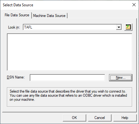
Select Configure-Master Database-Connect to MDB. In the File Data Source tab, select the existing DSN name and click OK.
Creating a New DSN
Select Configure-Master Database-Connect to MDB. In the File Data Source tab, click the New button.
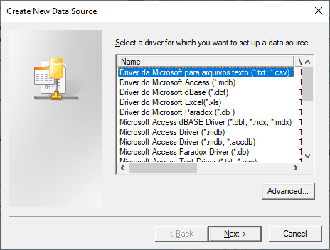
Select the applicable ODBC driver from the drop-down list and click the Next button.
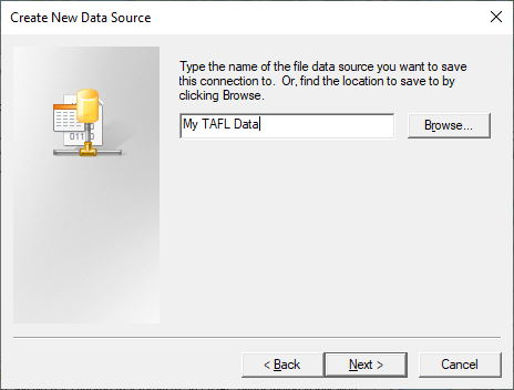
Enter a descriptive name for the data source and click the Next button.
A summary screen shows the status of the current DSN. Click the Finish button. At this point, the following description applies only to the Microsoft Access driver.
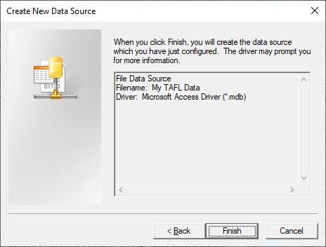
Click the Create button. A file save dialog box will appear. Select the directory and enter the specific name for this database and click the OK button. The file suffix will be “mdb” for Microsoft access databases.
When the notification that the database has been successfully created is acknowledged, click the OK button to close the ODBC Microsoft Access Setup dialog.
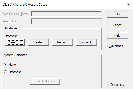
The display returns to the initial Select Data Source dialog. Select the newly created DSN and click the OK button to complete the setup. A new database has been created complete with the table definition and relational structure. This becomes the default database and is defined by a connect string. This connect string is saved in the PL50.INI file using the identifier “MDB_CONNECT_STRING” in the [MDB_ODBC_OPTIONS] group. When the program starts, this string is used to automatically reconnect the database.
Disconnecting from a DSN
To remove a database connection, select Configure-Master Database-Connect to MDB and click the Cancel button.
Adding Site and Frequency Data to the MDB
This procedure adds site and frequency data to the MDB from delimited or fixed width text files. The standard text import utility is used to define the specific data format. Details of this utility are given in the General Program Operation section. Only those steps which are unique to this import are covered here. Click Configure - Master database - Add site-frequency data to MDB and select the text file to begin the import.
Preliminary Considerations
As a minimum a site definition must include a name and its coordinates
If the site coordinates in the text file are specified as projected values e.g. a UTM easting, northing and zone, then this projection and the corresponding datum must be set in the Site tab in the GIS configuration.
The primary key field in the site table is derived from its latitude and longitude. For example the primary key for a site with the coordinates 56 16 33.67 N and 120 53 23.42 W will be N56163367W120532342. Therefore, if sites with the same coordinates to the nearest 0.01 second exist in the text file, then only the first site encountered will be added to the site table.
The import procedure does not check for duplicate frequencies or antennas at a site. If you are adding frequency data for interference calculations and the data is subject to frequent revisions, then you should always start with empty tables. Otherwise, duplicate entries will occur for each new revision added.
The first two panes set the delimiter and define the columns. These are common to all text import operations.
Column Assignments
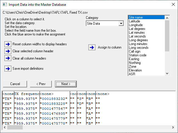
The third pane uses three categories to assign the data to the columns as follows:
- Click on a column
- Select the category
- Select the specific data item for the selected category
- Click the Assign to column button
The same procedure is used to import site, antenna and frequency data. A site only import would only use the Site category.
Text Import Options
The final pane contains numeric units and formatting options.
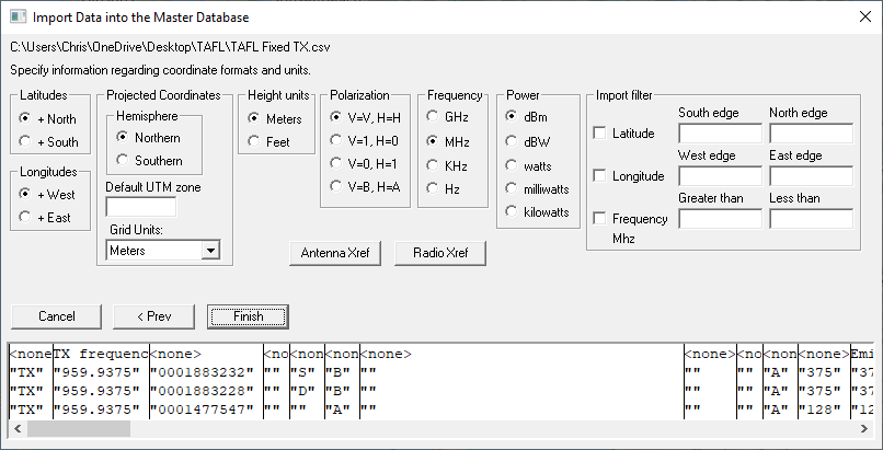
Site Coordinates
Hemisphere settings are only applicable to site coordinates specified as latitude and longitude.
If the latitudes in the file are positive and the site is in the Northern hemisphere, click +North.
If the longitudes in the file are negative and the site is in the Western hemisphere, click +East.
If the site coordinates are specified as projected values e.g UTM Easting, Northing and zone, the options shown on the right must be set. In addition, the Site tab in the GIS configuration must be set to this projection and the corresponding datum. These settings are used to convert the projected coordinates to latitude and longitude.
Specify the hemisphere that the sites are in. UTM projections can have the same values in the northern and southern hemispheres.
If the site coordinates are in a UTM projection and the text file does not contain a UTM zone field, then the Default UTM zone must be specified.
Specify the projection units.
Units
Specify the frequency, transmit power and elevation units in the text file.
Specify the polarization format. Note that if the frequencies in the file include a H-V polarization specifier, e.g. 8687.37500V, then the polarization will be set to this value.
Import filter
An import filter is provided to select sites in a certain geographic area and within a certain frequency range.
If a South edge is specified without a North edge, then only sites which are North of the South edge value will be imported.
If an East edge is specified without a West edge, then only sites which are West of the East edge will be imported.
Antenna and Radio Code Cross Reference
A prerequisite for interference calculations is the antenna pattern data. Interference calculations made in the Network display rely on the antenna codes specified in the individual pl5 data files. These codes reference the antenna data files and if they are not available, then the interference calculation will not proceed.
Similarly, radio data files are used to calculate the loss to an interfering signal due to the frequency separation between the victim receiver and the interfering transmitter. If this data is not available, the calculation will proceed; however, it may be necessary to limit the calculation to co-channel operation to avoid a large number of extraneous cases.
In the case of external frequency data, these antenna and radio codes may not be available. Several methods of handling this situation are available.
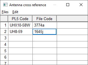
Antenna Cross Reference
The user can create a cross reference between an antenna field such as the antenna model in the text file and the actual antenna code. This column must be identified as the antenna code. As the import proceeds, the value specified in the file column designated as “antenna code” is checked against the cross reference table and the actual code will be substituted, if it is found.
Radio Cross Reference
The user can create a cross reference between a radio field such as the model in the file and the actual radio code. This column must be identified as the radio code. As the import proceeds, the value specified in the file column designated as “radio code” is checked against the cross reference table and the actual code will be substituted, if it is found.
Exporting Data From the Network Display to the MDB
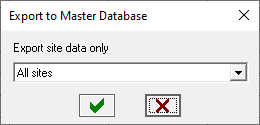
Three options are provided to export data from the Network display to the MDB. In the site list, click Export - Master Database and select either sites, links or base stations.
Export Site Data Only
Duplicate sites are not allowed in the MDB. The primary key field in the site table is derived from the site latitude and longitude. For example, the primary key for a site with the coordinates 56 16 33.67 N and 120 53 23.42 W will be N56163367W120532342. If the Network display includes several sites at the same location with different call signs, the site will only be added once. The call signs will be added to the associated station table.
The site, station and company table are used for site data.
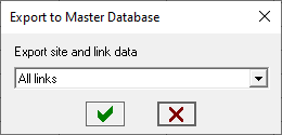
Export Site and Link Data
The sites portion of the link export follows the same rules as the sites only export. The link must include frequency assignments. When a link is exported the full path name of the associated Pathloss data file (pl5 file) is exported to the link table. The link may then be removed from the Network display; however, the pl5 file should not be moved or erased as the path profile is not imported into the database. If the link is subsequently imported back into the Network display, the file association will be maintained.
The link export starts with the antennas. The program checks all existing antennas at a site. If an antenna already exists at the same elevation and azimuth, then this is considered to be a duplicate and the link is not added.
In addition to the site tables, links data uses the antenna, frequency and link tables.
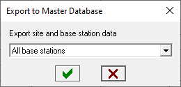
Export Site and Base Station Data
The sites portion of the base station export follows the same rules as the sites only export. Only base stations which include frequency assignments can be exported to the MDB. Mobile specifications are not exported.
The base station export starts with the antennas. The program checks all existing antennas at a site. If an antenna already exists at the same elevation and azimuth, then this is considered to be a duplicate and the base station is not added.
In addition to the site tables, base station data uses the antenna, frequency and base tables.
Importing Data From the MDB into the Network Display
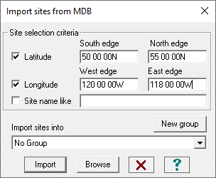
Sites, links and base stations can be imported into the Network display. In the Site List click Import - Master database. Each of these import procedures include a selection criteria to filter data in a certain region, frequency band or a particular site name. At least one of these selection criteria must be active to carry out the import.
- Latitude - Check the latitude box and enter the value for at least one edge. If the south edge is entered and the north edge is blank, then the import will include all items north of the south edge. If the north edge is entered and the south edge is blank, then the import will include all items south of the north edge.
- Longitude - Check the longitude box and enter the value for at least one edge. If the west edge is entered and the east edge is blank, then the import will include all items east of the west edge. If the east edge is entered and the west edge is blank, then the import will include all items west of the east edge.
- Frequency - Check the frequency box and enter at least one value for the frequency range.
- Site name like - Enter the site name or any portion of the name.
Sites, links and base stations can be imported into a group. Select the group in the drop down list or use the “No Group” selection to not use groups. A new group can be created with the New group button.
Import Sites
Click the import button to import sites directly into the Network display.
Alternately, click the Browse button to examine the sites in a browse list which shows all of the site fields.
To add the currently selected single site to the Network display, click the Import site(s) menu item.
To create a selection of sites to add to the Network display, click on the row number column. Use the Shift and Ctrl keys to select multiple sites. Then click the Import site(s) menu item.
Note that sites cannot be imported into a group from the browse list.
Import Links
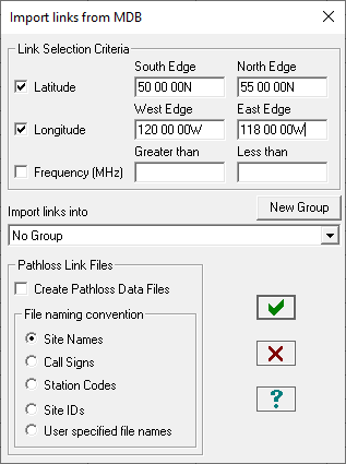
This procedure will import both sites and links into the Network display. A duplicate site will be created if all of the following conditions are met:
- A site exists in the Network display with the same coordinates as the MDB site
- The site has a call sign
- The MDB site has a different call sign
Otherwise, the Network display site will be used. If the MDB site has a call sign and the Network display does not, the MDB call sign will be used.
Note that the only method of adding links to the MDB is by exporting the links from the Network display. This can only be carried out if a Pathloss data file (pl5 file) with frequency assignments is associated with the link. The full path name of this pl5 file is saved in the MDB.
The Import link dialog contains an option to create a Pathloss data file for the link. All antenna and frequency/radio data would be saved in this file.
The link import procedure checks for the existence of the pl5 file. If this file exists, then this file will be used as the link file association and a new file will not be created.
Import Base Station
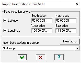
This procedure will import the base station site data into the Network display. Duplicate sites will be created under the conditions described in the above link import procedure.
The import only includes the base station antennas and equipment. The mobile antenna and radio equipment can be added to each base station or to a group of base stations using the Base station add edit feature.
MDB Table Structure
This section describes the table structure of the MDB tables.
Owner - Operator Table
|
Field |
Field Name |
Format |
Description |
|
1 |
COMPID |
CHAR[16] |
Primary key |
|
2 |
NAME |
CHAR[64] |
Owner or operator name |
|
3 |
ADDRESS1 |
CHAR[64] |
Address 1 |
|
4 |
ADDRESS2 |
CHAR[64] |
Address 2 |
|
5 |
CITY |
CHAR[64] |
City |
|
6 |
STATE |
CHAR[64] |
State or province |
|
7 |
COUNTRY |
CHAR[64] |
Country |
|
8 |
ZIPCODE |
CHAR[16] |
Zip or postal code |
|
9 |
CONTACT |
CHAR[64] |
Contact name |
|
10 |
TITLE |
CHAR[64] |
Contact’s position or title |
|
11 |
TEL |
CHAR[32] |
Telephone number |
|
12 |
FAX |
CHAR[32] |
FAX number |
|
13 |
|
CHAR[64] |
Email address |
Station Table
|
Field |
Field Name |
Format |
Description |
|
1 |
STATID |
INT32 |
Primary key |
|
2 |
CALLSIGN |
CHAR[16] |
Call sign - key field |
|
3 |
SITEID |
CHAR[24] |
Site ID - references pl50site |
|
4 |
COMPID |
CHAR[16] |
Operator ID - references pl50company |
|
5 |
STATCODE |
CHAR[16] |
Optional station identifier |
|
6 |
LICENSE |
CHAR[64] |
License identifier |
|
7 |
LICENSE_DATE |
INT32 |
License date - database specific format |
|
8 |
SERVICE_DATE |
INT23 |
In service date - database specific format |
|
9 |
COMMENT |
CHAR[256] |
Comments |
Site Table
The tower type field is defined as follows:
0 - unknown, 1 -self supporting, 2 - guyed, 3 - water tank, 4 - roof mount, 5 - building mount, 6 - monopole, 7 - other
|
Field |
Field Name |
Format |
Description |
|
1 |
SITEID |
CHAR[24] |
Primary key - based on site coordinates |
|
2 |
NAME |
CHAR[48] |
Site name |
|
3 |
LATITUDE |
DOUBLE |
Latitude rounded to 1/100 second |
|
4 |
LONGITUDE |
DOUBLE |
Longitude rounded to 1/100 second |
|
5 |
DATUM |
INT16 |
Datum number - predefined field |
|
6 |
ELEVATION |
DOUBLE |
Site elevation in meters |
|
7 |
ASR |
CHAR[16] |
Antenna structure record identifier |
|
8 |
TWR_TYPE |
BYTE |
Tower type - predefined field |
|
9 |
TWR_HGT |
DOUBLE |
Tower height in meters |
|
10 |
TWR_HGT_WAPP |
DOUBLE |
Tower height with appurtenances in meters |
|
11 |
ADDRESS |
CHAR[48] |
Address |
|
12 |
CITY |
CHAR[48] |
City |
|
13 |
STATE |
CHAR[24] |
State |
|
14 |
COUNTRY |
CHAR[24] |
Country |
|
15 |
ZIPCODE |
CHAR[16] |
Zip or postal code |
|
16 |
COMPID |
CHAR[16] |
Owner ID - references pl50company |
Passive Repeater Table
|
Field |
Field Name |
Format |
Description |
|
1 |
PASSID |
INT32 |
Primary key field |
|
2 |
SITEID |
CHAR[24] |
Site ID - references pl50site |
|
3 |
PASSTYPE |
INT08 |
Passive repeater type - predefined field |
|
4 |
AZIMUTH1 |
DOUBLE |
#1 Azimuth (degrees) |
|
5 |
AZIMUTH2 |
DOUBLE |
#2 Azimuth (degrees) |
|
6 |
ANTMODL1 |
CHAR[48] |
#1 Antenna model (back to back antennas) |
|
7 |
ANTGAIN1 |
DOUBLE |
#1 Antenna gain (dBi) |
|
8 |
ANTHGHT1 |
DOUBLE |
#1 Antenna height (meters) |
|
9 |
ANTCODE1 |
CHAR[48] |
#1 Antenna code |
|
10 |
ANTMODL2 |
CHAR[48] |
#2 Antenna model (back to back antennas) |
|
11 |
ANTGAIN2 |
DOUBLE |
#2 Antenna gain (dBi) |
|
12 |
ANTGHGT2 |
DOUBLE |
#2 Antenna height (meters) |
|
13 |
ANTCODE2 |
CHAR[48] |
#2 Antenna code |
|
14 |
TXLLOSS |
DOUBLE |
Antenna transmission line loss (dB) |
|
15 |
AMPGAIN12 |
DOUBLE |
Amplifier gain 1®2 (dB) |
|
16 |
AMPGAIN21 |
DOUBLE |
Amplifier gain 2¬1 (dB) |
|
17 |
WIDTH1 |
DOUBLE |
#1 Passive width (meters) |
|
18 |
HEIGHT1 |
DOUBLE |
#1 Passive height (meters) |
|
19 |
WIDTH2 |
DOUBLE |
#2 Passive width (meters) |
|
20 |
HEIGHT2 |
DOUBLE |
#2 Passive height (meters) |
|
21 |
SPACING |
DOUBLE |
Spacing between double passive (meters) |
|
22 |
PRGAIN |
DOUBLE |
Passive Repeater Gain |
Antenna Table
|
Field |
Field Name |
Format |
Description |
|
1 |
ANTID |
INT32 |
Primary key |
|
2 |
SITEID |
CHAR[24] |
Site ID references pl50site |
|
3 |
MODEL |
CHAR[48] |
Radio model |
|
4 |
CODE |
CHAR[48] |
Radio code (radio index file reference) |
|
5 |
GAINDBI |
DOUBLE |
Antenna gain (dBi) |
|
6 |
DIAMETER |
DOUBLE |
Antenna diameter (meters) |
|
7 |
BEAMWIDTH |
DOUBLE |
Antenna beamwidth (degrees) |
|
8 |
CLHEIGHT |
DOUBLE |
Antenna center line height (meters) |
|
9 |
AZIMUTH |
DOUBLE |
Azimuth as installed (degrees from true north) |
|
10 |
ELEVANG |
DOUBLE |
Elevation angle as installed (degrees) |
|
11 |
TRUAZIMUTH |
DOUBLE |
True azimuth (degrees) |
|
12 |
TRUELEVANG |
DOUBLE |
True elevation angle (degrees) |
|
13 |
TXLOSS |
DOUBLE |
Transmit side total loss (dB) |
|
14 |
RXLOSS |
DOUBLE |
Receive side total loss (dB) |
Link Table
The following predefined fields are used in the link table
Antenna configuration:
0 - TR_TR, 1 - TRDR_TRDR, 2 -TXRX_TXRX, 3 - TXRXDR_TXRXDR, 4 - TX_RX, 5 - TX_RXDR,
6 - RX_TX, 7 - RXDR_TX, 8 - TR_TRTH, 9 - TRTH_TR, 10 - TR_TXRX, 11 - TXRX_TR
Application type:
0 - conventional microwave, 1 - adaptive modulation, 2 - land mobile, 3 - broadcast
Point to point - Point to multipoint:
0 - point to point, 1 - point to multipoint, 3 - point from multipoint
|
Field |
Field Name |
Format |
Description |
|
1 |
LINKID |
INT32 |
Primary key |
|
2 |
ANTCONFIG |
BTYE |
Antenna configuration - predefined field |
|
3 |
APPTYPE |
BTYE |
Application type - predefined field |
|
4 |
PTPPTMP |
BTYE |
PTP or PTMP link - predefined |
|
5 |
S1ANTID1 |
INT32 |
Site 1 antenna ID1 - references pl50antenna |
|
6 |
S1ANTID2 |
INT32 |
Site 1 antenna ID2 - references pl50antenna |
|
7 |
S1ANTID2 |
INT32 |
Site 1 antenna ID3 - references pl50antenna |
|
8 |
S2ANTID1 |
INT32 |
Site 2 antenna ID1 - references pl50antenna |
|
9 |
S2ANTID2 |
INT32 |
Site 2 antenna ID2 - references pl50antenna |
|
10 |
S2ANTID3 |
INT32 |
Site 2 antenna ID3 - references pl50antenna |
|
11 |
PASSREP1 |
INT32 |
Passive repeater ID1 - references pl50passive |
|
12 |
PASSREP2 |
INT32 |
Passive repeater ID1 - references pl50passive |
|
13 |
PASSREP3 |
INT32 |
Passive repeater ID1 - references pl50passive |
|
14 |
FILENAME |
CHAR[260] |
Pathloss data file name (pl5) |
Base Station Table
|
Field |
Field Name |
Format |
Description |
|
1 |
BASEID |
INT32 |
Primary key |
|
2 |
APPTYPE |
INT8 |
Application type |
|
3 |
ANTID1 |
INT32 |
Sector 1 antenna ID |
|
4 |
ANTID2 |
INT32 |
Sector 2 antenna ID |
|
5 |
ANTID3 |
INT32 |
Sector 3 antenna ID |
|
6 |
ANTID4 |
INT32 |
Sector 4 antenna ID |
|
7 |
ANTID5 |
INT32 |
Sector 5 antenna ID |
|
8 |
ANTID6 |
INT32 |
Sector 6 antenna ID |
|
9 |
ANTID7 |
INT32 |
Sector 7 antenna ID |
|
10 |
ANTID8 |
INT32 |
Sector 8 antenna ID |
Frequency Assignment Table
The following predefined fields are used in the frequency assignment table:
Polarization:
0 - horizontal1, 1 - vertical, 2 - slant right, 3 - slant left, 4 - circular right, 5 - circular left
Duplex technology:
0 - FDD, 1 - TDD, 2 - TDD synchronized
Multiple access technology:
0 - FDMA, 1 - TDMA, 2 - CDMA, 3 - OFDMA, 4 - CSMA
|
Field |
Field Name |
Format |
Description |
|
1 |
ANTID |
INT32 |
Antenna ID - references pl50antenna |
|
2 |
LINKID |
INT32 |
Link ID |
|
3 |
BASEID |
INT32 |
Base station ID |
|
4 |
STATID |
INT32 |
Station ID - references pl50station |
|
5 |
TXFREQMHZ |
DOUBLE |
Transmit frequency (MHz) |
|
6 |
TXCHANID |
CHAR[16] |
Transmit channel descriptor |
|
7 |
TXPOLAR |
BYTE |
Transmit polarization - predefined field |
|
8 |
RXFREQMHZ |
DOUBLE |
Receive frequency (MHz) |
|
9 |
RXCHANID |
CHAR[16] |
Receive channel descriptor |
|
10 |
RXPOLAR |
BYTE |
Receive polarization - predefined field |
|
11 |
TXPWRDBM |
DOUBLE |
Transmit power (dBm) |
|
12 |
EMDESIG |
CHAR[16] |
Emission designator |
|
13 |
APCRANGE |
DOUBLE |
APC range (dB) |
|
14 |
RADIOMODEL |
CHAR[48] |
Radio model |
|
15 |
RADIOCODE |
CHAR[48] |
Radio code (radio index file reference) |
|
16 |
TRAFFCODE |
CHAR[16] |
Traffic code |
|
17 |
RXSIGDBM |
DOUBLE |
Receive signal (dBm) |
|
18 |
RXTHRSTR |
CHAR[48] |
Receiver threshold description |
|
19 |
RXTHRDBM |
DOUBLE |
Receiver threshold level (dBm) |
|
20 |
NSEFLRDBM |
DOUBLE |
Receiver noise floor (dBm) |
|
21 |
DUPLEX |
BYTE |
Duplex technology - predefined field |
|
22 |
MUACESS |
BYTE |
Multiple access technology - predefined fields |
|
23 |
STATUS |
CHAR[32] |
Status field |
Cross Reference Table
The cross reference table contains a single record of the last used primary key field ids for the station, antenna, passive, link and base station tables. This table is accessed and incremented whenever a new record is created for these tables.
When the MDB tables are first created, a unique number is created and saved in this table. When links are imported from the network display into the database, this unique number and the link id are saved in the network file. This is used to identify duplicate links and to update links.
|
Field |
Field Name |
Format |
Description |
|
1 |
XREFVER |
INT32 |
Table identifier - PL50 |
|
2 |
IDNUMBER |
INT32 |
Unique number for each database |
|
3 |
STATCNT |
INT32 |
Last station ID used |
|
4 |
ANTCNT |
INT32 |
Last antenna ID used |
|
5 |
PASSCNT |
INT32 |
Last passive ID used |
|
6 |
LINKCNT |
INT32 |
Last link ID used |
|
7 |
BASECNT |
INT32 |
Last base station ID used |