Pathloss Algorithm
The default settings are recommended for transmission applications. The algorithm can be configured for special applications or to compare the results with those of other programs.
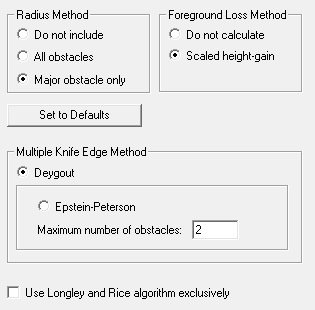
Radius Method
This setting refers to the radius calculation used by the isolated obstacle algorithm when the terrain is characterized as a single or multiple knife edge. The isolated obstacle algorithm is equivalent to a knife edge if the radius is not used.
No radius
The loss is always calculated as a single knife edge for single or multiple knife edge paths. The results are usually lower than the measured value.
All obstacles
A radius will be used for all obstacles. On multiple knife edge paths, this setting usually results in higher than measured value.
Major obstacle only
If the path contains a single obstacle, the radius will be used. In the case of multiple obstacles, the radius will only be applied to the major obstacle. The major obstacle is the one with the minimum clearance to first Fresnel zone ratio (C /F1). Note that the reference end points are different in the Deygout and Epstein & Peterson multiple knife edge models. In the Deygout model, the C /F1 is referenced to the end points of the profile. In the Epstein & Peterson model, the C/F1 is referenced to the horizons of the obstacle under test.
Multiple knife edge method
Deygout (default)
This model is limited to a double knife edge path. The clearance to first Fresnel zone ratio is calculated for each obstacle, with respect to the end points of the profile, to determine the major obstacle.
The loss of the major obstacle is calculated as a knife edge or isolated obstacle referenced to the end points of the profile, as if the second obstacle did not exist. The loss of the minor obstacle is then calculated with respect to its horizons. The resultant loss is the total of the two calculations.
Epstein & Peterson
In this model, there is no theoretical limit to the number of knife edges; however, the program has an internal limit of 10. The user can set an upper limit in the range 2 to 10. If this limit is exceeded, the Longley & Rice irregular terrain algorithm will be used.
The Epstein & Peterson model treats the terrain as a succession of knife edges. The loss of each knife edge is calculated using the horizons of the knife edge as the end points. The resultant loss is the sum of the individual knife edge calculations.
The results of the Deygout model will always be higher than the Epstein & Peterson model, and therefore, provides a conservative design approach. When the obstacles are widely separated, the Epstein & Peterson model is more accurate. When the obstacles are close together, the Epstein & Peterson model will seriously under-predict the loss.
Foreground loss method
When the terrain is characterized as a single or multiple knife edge, it is necessary to examine the terrain between an antenna and its horizon. If the clearance to first Fresnel zone ratio in this region is less than 60%, additional loss will occur and must be taken into account. This is referred to as the foreground loss.
This calculation is carried out using the height - gain algorithm and should always be used. An option to not calculate this loss is provided primarily as a means to compare the results with other programs.
Use Longley and Rice algorithm exclusively
If this option is selected, all diffraction loss calculations for line of sight and obstructed paths will use the Longley and Rice algorithm.