Terrain Roughness Calculation
In the Vigants - Barnett path profile data entry form, click the calculate button on the terrain roughness line. The Terrain Roughness calculation uses standard profile display screen formatted for flat earth. Refer to the General program operation section for details of this display.
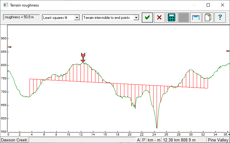
The user defines the start and end points on the profile over which roughness will be calculated. The roughness calculation interpolates 50 uniformly spaced points between the start and end points. Terrain roughness is defined as the standard deviation of the terrain elevations (square root of the average square of the deviation from the mean). Two calculation methods are available. In the first method, the elevations are referenced to sea level. In the second method, the elevations are referenced to a least squares fit (y = ax + b) of the terrain over the profile segment defined by the start and end points. This selection is made on the drop down list on the tool bar.
The roughness limits are 6 meters (20 feet) minimum and 42 meters (140 feet) maximum for the Vigants - Barnett reliability method. These limits are imposed when the roughness is transferred to the Path data entry form. Note that a terrain roughness calculation is also made in the Multipath - Reflections module. The limits of the Vigants - Barnett method do not apply to the in the Multipath - Reflections module
Significant differences will occur on paths with a uniform slope and an elevation difference between the end points greater than 40 meters. If the least squares method is used, the terrain roughness will be the minimum value. If the sea level reference is used, the terrain roughness will be the maximum value. In strict accordance with the original reference, "Space Diversity Engineering by A. Vigants", the elevations should be relative to sea level.
The Vigants-Barnett method does not take into account the path inclination. In practice, a high to low path, with an elevation difference of several hundred meters performs better than a flat path with the same terrain characteristics. If terrain roughness is calculated using a sea level reference, the higher terrain roughness is more applicable. However, if the elevation difference of the path is in the order of 50 meters and relatively flat, the least squares method should be used.
Status bar
The status bar shows the site names, cursor style and movement state, measurement system, and the cursor location.
To display the current terrain point data, click the left mouse button on the cursor location box or press the Ins key.
Automatic procedure
Click the calculate button on the tool bar. The program determines the range of points which are intervisible to both antennas. If this range if greater than 50% of the path length, terrain roughness is calculated over this range. Otherwise, terrain roughness is calculated over the central 80% of the path profile.
Manual procedure
- Place the arrow at one end of the profile segment over which terrain roughness is to be calculated and click the right mouse button.
- Move the arrow to the opposite end of the section and click the right mouse button again.
The Reset button is active when the first point has been selected. This will only cancel the first point selection.
To repeat a terrain roughness calculation, just reselect the end points of the new reflective plane. This is carried out over the existing calculation.
Click the OK button to accept the calculated value of terrain roughness. The Cancel button discards the calculation.