Radio, Antenna and Transmission Line Data
Overview
The Pathloss program uses two methods to organize radio and antenna specifications:
- The data is organized in tabular form (rows and columns). Each row in the table contains the specifications for one radio or antenna model. These are referred to as lookup tables in the program and are saved in individual files. The files can be distributed between users.
- The data is contained in individual files. A file is required for each radio or antenna model. A file indexing system is used to organize and access these files. These files can also be distributed between users. However, they must first be added to the file index to be used.
- The requirement for the second method (individual files) arises to handle more extensive data or data in a graphical format such as:
- The antenna gain as a function of the horizontal or vertical angle for different polarization combinations.
- The transmit emission or receiver selectivity as a function of frequency.
Antenna data files are required for the following applications and analysis:
- All interference calculations use the horizontal antenna pattern to calculate the antenna discrimination to the interfering signal. A pattern is used for each polarization combination (HH, VV, VH and HV)
- Dipole antennas are assumed to be mounted in a horizontal plane. Therefore, there will always be some degree of mis-orientation in the vertical plane. On a high - low path, this can be significant. A vertical plane antenna pattern is required to calculate this orientation loss.
- Base stations in point to mulitpoint design, local and area studies require antenna patterns in both the vertical and horizontal planes. For multi-sectored antennas, an antenna data file is specified for each sector.
- Carrier to interference calculations in an area study require the antenna pattern at the remote terminal or subscriber locations.
Radio data files are required for the following applications and analysis:
- All interference calculation require curves to calculate filter loss as a function of frequency and bandwidth differences between the interfering transmitter and victim receiver.
- Radio data files are required at base stations for carrier to interference calculations in an area study.
- Adaptive modulation radios require specifications for each modulation state. It is not practical to incorporate this level of data entry in a lookup table. A radio data file is required for these applications.
- The data requirements for BBER SES performance calculations are also considered to be outside the scope of a lookup table and a radio data file is required for these applications.
- Automated design optimization uses transmitter power options and the antenna coupling unit specification for space diversity antenna configurations. A radio data file includes this information and is required to used these optimizations.
Note that a lookup table includes a field for the data file name. This results in the simplicity of a lookup table with the complete analytic capability of the data files. If a data file name is included in the lookup table, then that file must be also included in the file index. Transferring a lookup table which includes data file names will result in errors messages stating that the data file cannot be found. This can be corrected by obtaining the data file and adding it to the file index. The error can be removed (but not corrected) by erasing the data file name from the lookup table.
Pathloss Radio and Antenna Data Files
The equipmnt directory in the Pathloss 5 program directory contains the currently available radio and antenna data files in the sub directories RSD (Radio Spec Data) and ASD (Antenna Spec Data). In order to use these files, they must first be added to the file index.
Antenna Data File Index
An antenna data file includes the basic specifications (gain, beam width, diameter) and a set of radiation patterns. A separate file is used for each antenna model. The antenna data file index provides a method of managing these files on the users computer. This is accomplished by assigning unique names for each antenna data file. If effect, the antenna file name less the suffix is a key field. In this scheme, the file names are always lower case. This means that antenna data files with the same name but located in different directories cannot be used. The maximum antenna file name length not including the suffix is 47 characters.
In order to use an antenna data file in the Pathloss program, it must first be converted to a binary format and then entered into the antenna index. The binary conversion is carried out in AntRad. Refer to the documentation for this program for details.
Initially, the antenna index will be empty. The procedure to add antenna files to the index is given below.
Pathloss 4 used different binary file formats for microwave and VHF-UHF antennas with the suffixes MAS and VAS, respectively. Pathloss 5 and 6 use a singe file format for all type of antennas with the suffix ASD. There is no need to convert the Version 4 files. These can be used as they are, along with the Pathloss 5/6 file format.
Adding Antenna Files to the Antenna Index
Click either Import Antenna Files or Import Folder Subfolders to create an index for the antenna data files.
- Import Antenna Files - Multiselect the desired files. Click Open to add these to the index.
- Import Folder Subfolders - Select the directory and click Open to add all files in the directory and subdirectories to the index.
The index file is automatically saved in \AppData\Roaming\Pathloss6\equipmnt\pl50_ant.ndx.
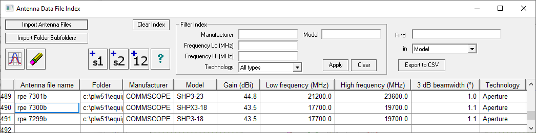
Antenna Index Tool Bar
The list of antennas can be filtered by the manufacturer, frequency range and technology. Enter values for any of these fields in the Filter Index group box on the tool bar and click the Apply button.
Note that the filter settings are saved and when the Antenna index is opened again, the list may be in a filtered state. If new antennas are added to the index which are not within the filter ranges, then they will be added but not displayed. This gives the impression that the import has failed for some reason. Before carrying out an import click Clear in the Filter Index box.
In addition to the filter, the antenna list can be searched for a specific manufacturer, code or model. Select the search criteria in the Find in drop-down list and enter the value. The search is incremental and will change as each character is entered.
 To view the antenna patterns and specifications for a specific antenna, place the cursor on the desired antenna and click the display button.
 The antenna index is used to add antenna data into the various data entry forms throughout the program. The add buttons shown are for a link. The +1 and +2 buttons add the selected antenna into the site 1 and site 2 respectively. The +12 button adds the antenna into both sites.
Antenna Data Lookup Tables
 Antenna lookup tables are provided as an extension to the antenna file index and for those cases where the manufacturer’s antenna data file is not available.
There is only one antenna index; however, there can be any number of antenna lookup tables. The last used lookup table is automatically loaded each time the program starts.
Pathloss 4 used separate lookup tables for microwave and VHF-UHF antennas with the file suffixes MAT and VAT, respectively. Version 5 and 6 use a single file for all antenna types with the suffix ANT. All Pathloss 4 antenna lookup table files can be read.
The antenna lookup table uses the standard grid control data entry form with the following fields:
- Manufacturer
- Model
- Antenna data file name
- Technology
- Gain
- 3dB beam width
- Diameter
- High frequency
- Low frequency
Lookup table data can be read from the Antenna Data File Index. Open the Lookup Table from within the Transmission Analysis module by clicking the Antenna Icon and then the Antenna Data Lookup Table icon. Select Operations - File Index. Multiselect the required antenna models in the antenna index and click the Add (+) button. Note: This function is only available when accessing the index from within the Lookup Table.
If an antenna lookup table item contains an antenna data file name and this file is not in the index, then an error message results each time that item is used. If the file is not available, erase the antenna data file field.
Radio Data File Index
A radio data file includes the basic specifications and a set of curves which are used in an interference calculation.
A separate file is used for each radio model. The radio data file index provides a method of managing these files on the users computer. This is accomplished by assigning unique names for each radio data file. If effect, the radio file name less the suffix is a key field. This means that radio data files with the same name but located in different directories cannot be used. The maximum radio file name length not including the suffix is 47 characters.
There is no industry standard for radio data files. Pathloss 4 used an ASCII and binary file format for microwave applications only with the file suffixes RAF and MRS. These files can be used directly in Pathloss 5/6 without any changes. The Pathloss 5/6 radio data files supports adaptive modulation and land mobile in addition to microwave applications. The files are created (ASCII and binary) in AntRad. Refer to the documentation for this program for details.
In order to use a radio data file in the Pathloss program, it must first be converted to a binary format and then entered into the radio index. Initially, the radio index will be empty. The procedure to add radio files to the index is given below.
Radio data files that are supplied with the program are located in the Pathloss 6 program directory under equipmnt\rsd.
Importing Radio Data into the Index
Click either Import Radio Files or Import Folder Subfolders to create an index for the radio data files.
- Import Radio Files - Multiselect the desired files. Click Open to add these to the index.
- Import Folder Subfolders - Select the directory and click Open to add all files in the directory and subdirectories to the index.
The index file is automatically saved in \AppData\Roaming\Pathloss6\equipmnt\pl50_rad.ndx.
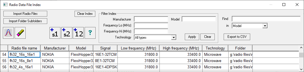
Radio Index Tool Bar
The list of radios can be filtered by the manufacturer, frequency range and technology. Enter values for any of these fields in the Filter Index group box on the tool bar and click the Apply button.
Note that the filter settings are saved and when the radio index is opened again, the list may be in a filtered state. If new radios are added to the index which are not within the filter ranges, then these will be added but not displayed. This gives the impression that the import has failed for some reason. Before carrying out an import, clear the filter settings. Erase the Manufacturer, Frequency Lo and Hi fields and set the Technology to All types. Then click the Apply button.
In addition to the filter, the radio list can be searched for a specific manufacturer, file name or model. Select the search criteria in the Find in drop-down list and enter the value. The search is incremental and will change as each character is entered.
To view the specifications and curves for a specific radio, place the cursor on the desired radio and click the display button.
The radio index is used to add radio data into the various data entry forms throughout the program. The add buttons shown are for a link. The +1 and +2 buttons add the selected radio into site 1 and site 2, respectively. The +12 button adds the radio into both sites.
If the radio data file is a an adaptive modulation application then further options will be presented as shown on the left. The options depend on the selected method ANSI (American National Standards Institute) or ETSI (European Telecommunications Standards Institute)
The display shows the modulation, data rate and RSEC for each modulation state.
The transmit power options are available for both ANSI and ETSI methods. Select the power option from the drop-down list and the options for all modulation states will be displayed.
In the ETSI method only, the user selects the desired modulation states and specifies the reference state. This is the modulation state which will be used in interference calculations. In any of the automatic design operations which involve optimization, the reference state will determine the optimization.
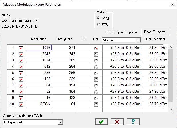
Note that the transmit power options, include an ATPC specification for each modulation level. In the ANSI method this would only be applicable to the top modulation. In the ETSI case, the ATPC would be applicable to the top modulation which has been checked.
Note that it is possible to select any combination of modulation states. Depending on the particular radio, a non continuous selection may not be allowed.
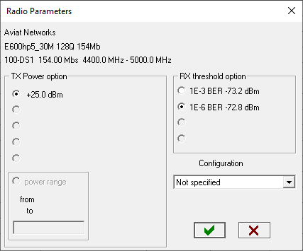
In microwave and land mobile applications, options are presented if the radio data file includes transmit power options or receiver threshold options, the user must select / set the following parameters to be used in the calculation:
- Transmit power option - if the radio data file includes a transmit power range specification, the user will enter the specific transmit power
- Receive threshold option
- Antenna coupling unit (radio configuration)
Radio Data Lookup Tables
Radio lookup tables are provided as an extension to the radio file index and for those cases where the radio data file is not available.
There is only one radio index; however, there can be any number of radio lookup tables. The last used lookup table is automatically loaded each time the program starts.
All Version 4 and 5 radio lookup tables (MRD) files can be read.
The radio lookup table uses the standard grid control data entry form with the following fields:
- Manufacturer
- Model
- Radio data file name
- Emission designator
- Technology
- TX power (dBm)
- RX threshold criteria
- RX threshold level (dBm)
- Maximum receive signal (dBm)
- Dispersive fade margin (dB)
- Modulation
- Capacity
- Signal standard
- High frequency
- Low frequency
Lookup table data can be read from the radio data file index. Select the Operations - Radio file index menu item. Multiselect the required radio models in the radio index, and click the Add (+) button.
If an radio lookup table item contains a radio data file name and this file is not in the index, then an error message results each time that item is used. If the file is not available, erase the radio data file field.
Transmission Line Index
The transmission line index contains the following data:
- Manufacturer - model - technology (elliptical waveguide, foam and air dielectric heliax), rigid wave guide and generic coaxial cable).
- Frequency range.
- Table of frequency versus loss in dB /100m.
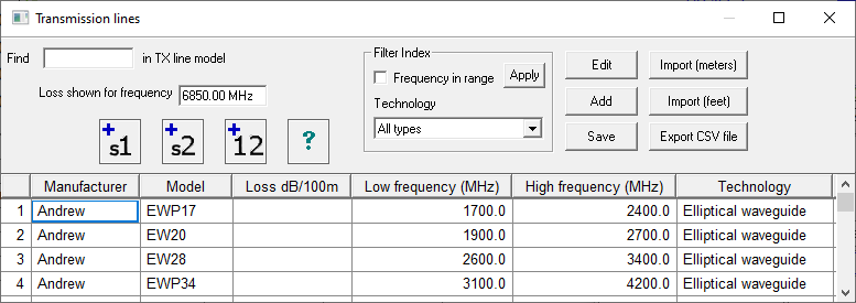
The values in the loss column are calculated on entry using the design frequency. A blank loss means that the frequency is outside the frequency range. If the frequency in the Loss shown for frequency edit control is changed, the loss values will be recalculated; however, the design frequency is not changed.
The table can be filtered by frequency or technology. For frequency, check the “Frequency in range” box and click the Apply button. For technology, select the technology from the drop down list and click the Apply button.
If the model number is known, enter this in the Find in TX line model edit control and the display will scroll to that model.
The transmission index is used on for data entry throughout the program. The add buttons shown are for a radio link. The +1 and +2 buttons add the selected transmission line into site 1 and site 2, respectively. The +12 button adds the transmission line into both sites.
Adding a New Transmission Line
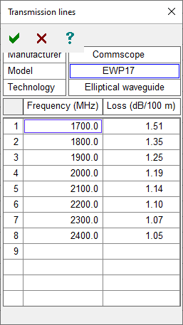 Click the Add button to add a new transmission line to the table. This form is suitable for adding a small number of transmission lines. The Import feature will add new transmission lines from a CSV files.
Enter the manufacturer model and technology in the upper section and at least two values of frequency and unit loss. The unit loss must be expressed in dB/100 meters.
The maximum and minimum frequencies are taken as the first and last entries in the list.
Editing an Existing Transmission Line
Place the cursor on the required entry and click the Edit button. The procedure is exactly the same as for the Add button described above.
Import
New transmission line data can be imported into the table from a comma delimited text file. The required file format is given below:
TXLINES50_INDEX
Generic,9913,5,6,50.0,2.10,100.0,3.28,200.0,5.25,400.0,8.20,700.0,11.81,900.0,13.78
Ajax,AJA5-50,2,4,960.0,3.67,1500.0,4.70,1700.0,5.04,2000.0,5.53
- The first line must be TXLINES50_INDEX. This is used as a file identifier. The following lines contain the data separated by commas.
- Manufacturer char[48]
- Model char [48]
- Transmission line type 0-Not specified, 1-Heliax air dielectric, 2-Heliax foam dielectric, 3-Elliptical waveguide, 4-Rigid wave guide, 5-Coaxial cable
- Number of frequency - loss pairs used to define the attenuation versus frequency curve. There must be at lease 2 pairs.
- The (frequency, unit loss,) data follows to complete the entry. Frequency must be in MHz. The unit loss can be in either db/100m of db/100ft.
If the file is created in Excel, then each line in the resulting CSV file will have the same number of commas as the maximum line length as shown in the example below:
TXLINES50_INDEX,,,,,,,,,,,,,,,
Generic,9913,5,6,50,2.1,100,3.28,200,5.25,400,8.2,700,11.81,900,13.78
Ajax,AJA5-50,2,4,960,3.67,1500,4.7,1700,5.04,2000,5.53,,,,
Click the Import (meters) button if the unit loss is in dB/100m or the Import (feet) button if the unit loss is in dB/100ft. Open the CSV file to import the data. The import procedure checks the existing data for duplicates. An entry is considered to be a duplicate if the manufacturer and model number are the same. Duplicate entries are not added; and therefore, this import cannot be used to edit existing data. If the new transmission line data does not appear at the bottom or the list, then check if the data is filtered using the Frequency in range or Technology field.
The data is automatically saved in equipmnt\pl50_txl.ndx.