AntRad
AntRad is an Editing and Conversion Tool for Pathloss Radio and Antenna Data Files.
This documentation describes the radio and antenna data ASCII file formats used in Pathloss 4, 5 and 6 programs. These ASCII files can be created programmatically, or individually with a text editor. AntRad edits and converts the ASCII files to the binary format required for the Pathloss program.
All Pathloss 4 radio and antenna files can be used unchanged with the Pathloss 5/6 programs. The Pathloss 5/6 format offers more flexibility for new data files and is required for adaptive modulation and land mobile radio data files. AntRad can be used to convert Pathloss 4 files to the Pathloss 5/6 format.
Pathloss 5/6 Radio Data Files
The Pathloss 5/6 programs use a proprietary ASCII radio data file format for conventional microwave, adaptive modulation and land mobile radio applications. Pathloss 4 radio data files are only applicable to conventional microwave radio. These files can be used in Pathloss 5/6 microwave applications without modification.
File Naming Convention
The radio data file name without the extension is used as a key field in a lookup table. Therefore, file names must be unique. The maximum radio file name length is 47 characters. File naming strategy becomes an important issue in this arrangement. A suggested format is given by the example “ACMELINK-6GHz-16E1-QPSK. This name consists of a manufacturer - model, frequency band, capacity and modulation.
The radio data file name is also used as an identifier for T to I and IRF curves. For example, an IRF curve could be identified as follows:
IRF_same 24 File_name1, File_name2, File_name3
This means this IRF curve is applicable to an interfering radio with the same file name as the radio being defined. In addition the curve is applicable to radios with file names File_name1, File_name2 and File_name3. The number 24 is the number of points in the curve.
File Formats
The first line in the file is PL50_ASCII_RADIO_SPEC_04. This is used as the file identifier and the revision number for the specific file format. Each successive line begins with a descriptive mnemonic followed by a semicolon and one or more data fields separated by a comma. A single data entry does not have any commas. Comments are denoted by a double forward slash //. All text after the // on the same line is ignored. A description of each mnemonic follows.
Fields designated as information only can be used for any specific purpose. All information in the radio data file except the curve data is also saved in the individual PL5/6 files
General Information
MANUFACTURER: - Radio equipment manufacturer
Text - 47 characters - required field
MODEL: - Radio model
Text - 47 characters - required field
RELEASE_DATE: - Original radio data release date
Text - 23 characters - information only
REVISION_NUM: - radio data revision number
text - 35 characters - information only
REVISION_DATE: - radio data revision date
text - 23 characters - information only
RADIO_ID: manufacturers radio identification
text - 47 characters - information only
PL50_RADIO_CODE: - the file name of the radio data file less the extension
text - 47 characters - this field is automatically created in the AntRad program using the file name
APPLICATION_TYPE: - the type of application
integer - 1 - microwave 2 - adaptive modulation 3 - land mobile - required field
RADIO_TYPE: - radio type description e.g SDH, PDH, Digital Video
text - 23 characters - information only
FREQUENCY_RANGE: - low frequency in MHz, high frequency in MHz
real number - required fields
EMISSION_DESIGNATOR: - radio equipment emission designator
text - 23 characters - used for default radio data files in interference calculations using the MDB
TXDATA_RATE_MBS: - data rate in Mb/s
real number - required field
RXDATA_RATE_MBS: - data rate in Mb/s
real number - required field
RADIO_CAPACITY: - number of lines, signal standard e.g. 4, E1
text - 15 characters - required field
MODULATION: - modulation type e.g. 128TCM
text - 15 characters - required field
BANDWIDTH_FCC_MHZ: - Bandwidth used to calculate the FCC spectrum mask in MHz
real number - information only
BANDWIDTH_99PC_MHZ: - Bandwidth containing 99% of the transmitter power
real number - information only
BANDWIDTH_3DB_TX_MHZ: - 3 dB transmit power bandwidth
real number - required field - used to calculate the default transmitter emission mask for interference calculations
BANDWIDTH_3DB_RX_MHZ: - 3 dB receiver selectivity bandwidth
real number - required field - used to calculate the default receiver selectivity mask for interference calculations
BANDWIDTH_CHANNEL_MHZ: - the assigned channel bandwidth in MHz
real number - information only
Transmitter Specifications
The specifications described in this section only apply to conventional microwave and land mobile applications. Adaptive modulation applications are separate and require specifications for each modulation state.
A total of 5 transmitter power options can be specified. This applies to discreet power options. Each option consists of the following parameters:
- Option name
- Maximum transmit power
- Minimum transmit power
- Automatic transmit power control range
The order must be the same on each line. The first option is the default TX power option.
TX_POWER_OPTIONS_NAME:
text 15 characters for each option - A maximum of 5 options can be specified on a single line separated by a single comma. e.g. Standard, Low, High, ,
The same power option names are used for all radio types: conventional microwave, adaptive modulation and land mobile
TX_POWER_OPTIONS_DBM:
real numbers - discreet transmit power options in dBm separated by commas. This is the maximum power for the specific option. At least one value of transmit power is required unless TX_POWER_RANGE_DBM is used.
TX_POWER_MIN_OPTIONS_DBM:
real numbers - This is the corresponding minimum TX power to the above maximum values
ATPC_OPTIONS_DB:
real numbers - This is the fixed ATPC values corresponding maximum and minimum TX powers above
TX_POWER_OPTIONS_NAME:
Hi, Std, Lo, Extra Hi, Extra Lo
TX_POWER_OPTIONS_DBM:
32.00, 30.00, 28.00, 34.00, 26.00
TX_POWER_MIN_OPTIONS_DBM:
25.00, 24.00, 23.00, 22.00, 21.00
ATPC_OPTIONS_DB:
15.00, 14.00, 13.00, 12.00, 11.00
TX_POWER_RANGE_DBM: This option is used for radios with a single adjustable transmit power range
real numbers - low power and high power in dBm separated by a comma - required field unless TX_POWER_OPTIONS_DBM is used - This is not used in adaptive modulation applications
ATPC_RANGE_DB:
real number - ATPC value corresponding the TX_POWER_RANGE_DBM above
ATPC_STEP_SIZE_DB:
real number - information only
REQUIRED_RXSIGNAL_DBM:
real number - All ATPC specifications presented above represent a fixed transmit power reduction, which will be applied in an interference calculation. The resultant power level cannot be less than the minimum power specified. In the case of the REQUIRED_RXSIGNAL option, the transmit power of the associated transmitter will automatically be reduced to meet the specified RX signal level. This option is only active if a value is specified for this option.
TX_STABILITY_PERCENT: transmitter frequency stability in percent
real number - information only
Receiver Specifications
Receiver specifications are keyed to a specific bit error rate. Provision for four bit error rates are available. These are operated by commas on the same line. The default BER values are 10-3, 10-6, the residual BER and the special SES BER used in SDH radio performance calculations.
These receiver specifications are not used in adaptive modulation applications; however, some noise floor calculation methods require the RX threshold level
RX_THRESHOLD_DESCRIPTION: a description of the receiver threshold e.g. BER 1E-3, 12 dB SINAD...
text 15 characters - used in some reports
RX_THRESHOLD_BER: the numerical value of the BER e.g 1.0E-3
real number - required for some ITU availability algorithms
RX_THRESHOLD_DBM: the receiver threshold level in dBm corresponding to the above threshold description
real number - required for microwave and land mobile applications
MAXIMUM_RXSIGNAL: the maximum receive signal level in dBm corresponding to the above threshold description
real number - optional field
DISPERSIVE_FM: dispersive fade margin in dB corresponding to the above threshold description
real number - required field for selective fade calculations using the dispersive fade margin
SIGNATURE_DELAY_NS: signature delay in nanoseconds corresponding to the above threshold description
real number - required field for selective fade calculations using the equipment signature method
SIGNATURE_WIDTH_MHZ: signature width in MHz
real number - required field for selective fade calculations using the equipment signature method
SIGNATURE_MINPHASE_DB: signature null depth in dB in the minimum phase condition
real number - required field for selective fade calculations using the equipment signature method
SIGNATURE_NONMINPHASE_DB: signature null depth in dB in the non-minimum phase condition
real number - required field for selective fade calculations using the equipment signature method
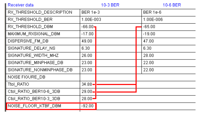
Specifications used for Noise Floor Calculations
Calculating threshold degradation due to interference requires the receiver noise floor level. This parameter can be specified directly or calculated from several parameters. The noise floor is used for all radio types.
NOISE_FIGURE_DB: receiver noise figure in dB
real number - The BANDWIDTH_3DB_RX_MHZ must be specified
TtoI_RATIO: C/I for a 1 dB degradation to the 10-6 BER RX threshold
real number - the RX_THRESHOLD_DBM field must include a value for the 10-6 BER
CtoI_RATIO_BER10-6_3DB: C/I for a 3 dB degradation to the 10-6 BER RX threshold
real number - the RX_THRESHOLD_DBM field must include a value for the 10-6 BER
CtoI_RATIO_BER10-3_3DB: C/I for a 3 dB degradation to the 10-3 BER RX threshold
real number - the RX_THRESHOLD_DBM field must include a value for the 10-3 BER
See the section Noise Floor Calculations for specific details.
Miscellaneous Specifications
SIMULCAST_CAPTURE_RANGE: receiver simulcast capture range in dB
real number - required for simulcast delay calculations in land mobile applications - the default value is 15 dB.
BITS_BLOCK: bits per block in an SDH radio
integer - required for BBER and ESR in SDH radio systems
BLOCKS_SEC: blocks per second in SDH radio
integer - required for BBER and ESR in SDH radio systems
ALPHA_VALUES: parameters describing the number of errors per burst in a an SDH radio
3 integer values separated by commas where:
a1 - number of errors per burst for a BER in the range 10-3 to the SES BER - typical values 10 to 30
a2 - number of errors per burst for a BER in the range from the SES BER to the residual BER - typical values are 1 to 10
a3 - number of errors per burst for a BER lower than the residual BER - a typical value is 1
COCHANNEL_OPERATION: enables or disables co-channel operation
integer 0 - disable co-channel operation, 1 - enable co-channel operation
COCHANNEL_XPIF: co-channel improvement factor
real number - applicable only if the radio is equipped with a co-channel improvement device
COCHANNEL_XPD_XPI: cross polarized discrimination of the co-channel improvement device
real number - applicable if the co-channel improvement device is a hardware implementation.
SELECTIVE_FADING: sets the selective fading calculation method
integer 0 use dispersive fade margin, 1 use equipment signature, 2 do not calculate selective fading
Space Diversity Improvement Parameters
SPACE_DIV_OPERATION: sets space diversity operation to either baseband switching or IF combining
integer 0 baseband switching, 1 IF combining
GAIN_WIDTH_DEPTH: three parameters used in space diversity using IF combining. The improvement to the selective fading can only be evaluated when the equipment signature is used.
IF combiner gain - default value is 2.6 dB. The gain is added to the thermal fade margin
Sig width factor - the signature width is multiplied by the width factor
Sig depth factor - both the signature minimum phase and non-minimum phase null depth are multiplied by this factor
Minimum Frequency Separation
T-T_FREQ_SEP_1ANT_CPOL: minimum transmitter to transmitter spacing using 1 antenna same polarization
real number - optional - information only
T-T_FREQ_SEP_1ANT_XPOL: minimum transmitter to transmitter spacing using 1 antenna cross polarized
real number - optional - information only
T-T_FREQ_SEP_2ANT_CPOL: minimum transmitter to transmitter spacing using 2 antenna same polarization
real number - optional - information only
T-T_FREQ_SEP_2ANT_XPOL: minimum transmitter to transmitter spacing using 2 antennas cross polarized
real number - optional - information only
T-R_FREQ_SEP_1ANT_CPOL: minimum transmitter to receiver spacing using 1 antenna same polarization
real number - optional - information only
T-R_FREQ_SEP_1ANT_XPOL: minimum transmitter to receiver spacing using 1 antenna cross polarized
real number - optional - information only
T-R_FREQ_SEP_2ANT_CPOL: minimum transmitter to receiver spacing using 2 antennas same polarization
real number - optional - information only
T-R_FREQ_SEP_2ANT_XPOL: - minimum transmitter to receiver spacing using 2 antennas cross polarized
real number - optional - information only
T-R_FIXED: fixed transmitter to receiver spacing
real number - optional - information only
Adaptive Modulation Specifications
Effective Threshold Concept
Adaptive modulation specifications use the concept of dynamic switching thresholds illustrated in the diagram on the right. Suppose the system is in the 1024QAM state and begins to fade. At what signal level will the radio switch down to 512QAM? If the switch does not occur until the signal level reaches the 1024QAM threshold level, errors will occur during the transition. Therefore, there must be some margin which will depend on the fade rate and the modulation state switching time.
The green line shows the transition between states as the signal level continues to fade.
When the system recovers from the fade, the reverse situation occurs. At what signal level would a signal in the 512QAM state switch to the 1024 state. If the switch occurred at the 1024QAM threshold level, errors would occur and again a similar margin is necessary. This is referred to as the step-up level. The red line shows the transition states as the signal returns to its unfaded state.
Note that the signal can never reach its 10-6 BER RX threshold except at the lowest modulation state (32 QAM) in the diagram.
For all other states, it is necessary to define an effective threshold as the average of the step-down level of a modulation and the step-up level of the next lower modulation state. These are the thresholds used in all performance calculations
| Modulation | 10-6 BER RX threshold level dBm | Step Down Level dBm | Step Up Level dBm | Effective RX Threshold dBm |
|---|---|---|---|---|
|
1024QAM |
-62 |
-59 |
|
-59.5 |
|
512QAM |
-65 |
-62 |
-60 |
-62.5 |
|
256QAM |
-68 |
-65 |
-63 |
-65.5 |
|
128QAM |
-71 |
-68 |
-66 |
-68.5 |
|
64QAM |
-74 |
-71 |
-69 |
-71.5 |
|
32QAM |
-77 |
|
-72 |
-77 |
In addition to the RX threshold level, the selective fading parameters (dispersive fade margin, and equipment signature are also affected by this margin. Provision has been made to provide specifications at both the 10-6 BER and the step levels.
Adaptive Modulation File Format
When using AntRad to fill out adaptive modulation data, a minimum of Modulation, Throughput, TX Power, and RX Threshold are required in order to advance to the next line and for the program to save the data.
The adaptive modulation starts with the mnemonic:
NUM_ACM_STATES: the number of adaptive modulation states
integer -there is no limit to the number of modulation states
The data is organized in three sections using the labels ADMOD_A, ADMOD_B and ADMOD_C. Each section must have the specified number of ACM states. Lines within a section are labelled with sequential numbering e.g ADMOD_A01, ADMOD_A02, ADMOD_A03
ADMOD_A:
Mod |
Modulation | Description e.g. 128 QAM | text - 15 characters |
RSEC |
RSEC | Radio spectrum efficiency class -ETSI requirement | text - 15 characters |
BER10-6 |
RX Threshold | 10_6 BER | real number - dBm |
SwUp |
Step Up Level | real number - dBm | |
SwDown |
Step Down Level | real number - dBm | |
Min C/I |
Minimum Carrier to Interference | This term is not used | real number |
Capacity |
Throughput Description | text - 15 characters |
E.g.:
//MOD_A: Mod, RSEC, BER10-6, SwUp, SwDown, Min C/I, Capacity

ADMOD_A01: 128QAM, 5B, -65, -55, -61, , 154
ADMOD_B:
dfm10_6 |
Dispersive fade margin | 10_6 BER threshold | real number - dB |
dfm_step |
Dispersive fade margin - step level | real number - dB | |
width |
Signature width | real number - MHz | |
sig_del |
Signature delay | real number - nanoseconds | |
minph10_6 |
Signature depth minimum phase | 10_6 BER threshold | real number - dB |
nminph10_6 |
Signature depth non-minimum phase | 10_6 BER threshold | real number - dB |
minph_step |
Signature depth minimum phase - step level | real number - dB | |
nminph_step |
Signature depth non-minimum phase - step level | real number - dB | |
max_rxsig |
Maximum RX signal | real number - dBm | |
XPIF |
XPIF - Cross polarized improvement factor | real number - dB |
E.g.:
// ADMOD_B:dfm10_6, dfm_step, sig_del, width, minph10_6, nminph10_6,

ADMOD_B01: 45, 48, 6.3, 28, 25, 24,

minph_step, nminph_step, max_rxsig, XPIF

28, 27, -16, 12
ADMOD_C:
Five transmit power options can be assigned to each modulation state Each power option consists of a maximum and minimum transmit power, and the top level ATPC.
E.g.:
//ADMOD_C: TXmax, TXmin, ATPC top, , , , , , , , , , , ,

ADMOD_C01: 30, 20, 10, 25, 15, 10, 32, 10, 10, , , , , ,
Radio Configuration and Antenna Coupling Unit
This section specifies the available radio configurations (e.g. monitored hot stand-by, space diversity..) and the associated antenna type and antenna coupling unit losses. Any number of configurations can be specified. There is no fixed limit.
Each configuration consists of a description, the antenna type (TR, TD, TH, TX and RX, and the associated losses in dB separated by commas. This information is used as a radio configuration lookup table in the Transmission Analysis module. For microwave and adaptive modulation applications the loss coding is as follows:
- CRC: Circulator branching loss
- TXS: TX switch loss
- TXF: TX filter loss
- RXH: RX hybrid loss
- RXF: RX filter loss
- DRC: Diversity RX circulator loss
For land mobile applications the loss coding is as follows:
- CRC: Duplexer loss
- TXS: TX combiner loss
- TXF: TX filter loss
- RXH: RX multicoupler loss (use negative values for gain)
- RXF: RX filter loss
configuration text 31 characters - real numbers representing loss values separated by commas
NUM_ACU_CONFIG:
//ACU: Configuration, ANT, CRC, TXS, TXF, RXH, RXF, DRC

ACU_CNFG_01: Unprotected, TR, 1.10, , 1.20, , 1.30,

ACU_CNFG_02: Hot Standby, TR, 1.10, 1.20, 1.30, 1.40, 1.50,
Miscellaneous:
COMMENT_1 - 6: General comments
text 47 characters - information only
Interference Curves - Conventional Microwave Radio
If the bandwidth or frequency of an interfering signal is different than the victim receiver, the filter improvement factor must be calculated. Two types of curves can be used to handle the case of different frequencies with the same bandwidth:
- TtoI curves - threshold to interference
- IRF curves - Interference reduction factor
Either format can be used. The curves can be single sided (0 to f_max) or double sided (f_min to f_max).
The general formats are as follows:
The interfering radio is the same as the radio specified in this file
TtoI_Same
IRF_Same
Suppose this same curve is valid for other several other radios
TtoI_Same other_radio_file1, other_radio_file2, . . .
IRF_Same other_radio_file1, other_radio_file2, . . .
where the names other_radio_file1 and other_radio_file2 are the interfering radio data file names i.e. the binary file names less extension of the interfering radio data files.
Suppose curves are required for several other different radios interfering with the radio specified in this file
TtoI_Other other_radio_file1, other_radio_file2, . . .
IFR Other other_radio_file1, other_radio_file2, . . .
In the case of bandwidth, a wide band transmitter interfering with a narrow band receiver is different than a narrow band transmitter interfering with a wide band receiver even if the frequencies are the same
The file format starts with a mnemonic (TtoI_Same, IRF_Same, TtoI_Other or IRF_Other) followed a colon and the number of points in the curve on the same line. If this curve is applicable to other radios, then list these on the same line separated by a comma. The data points follow with the frequency and the response in dB separated by a comma. Partial examples of a T to I curve and an IRF curve are given below:
TtoI_Same: 45, optional_other_filename1, optional_other_filename2

0.0, 28.0

0.5, 28.0

1.0, 28.0

2.0, 26.0

3.0, 23.0

4.0, 17.9

5.0, -7.1

10.0, -19.5

IRF_Same: 81, optional_other_filename1, optional_other_filename2

0.00, 0.00

1.00, -0.03

2.00, -0.11

3.00, -0.24

4.00, -0.42

5.00, -0.64

6.00, -0.91

7.00, -1.21

8.00, -1.56
The main advantage of TtoI and IRF curves is the speed of calculating the filter improvement as this can be read directly from the curve. The disadvantage is the large number of curves required for an interference calculation in a large network.
Transmitter Emission and Receiver Selectivity Curves
Any combination of bandwidth, modulation and frequency difference can be calculated with these two curves.
Transmitter Emission
The file format is the mnemonic TX_EMISSION followed by a colon and the number of points in the curve. The TX emission curve will be normalized for a total power of one watt based on a measurement bandwidth of 4 kHz.
Receiver Selectivity
The file format is the mnemonic RX_SELECTIVITY followed by a colon and the number of points in the curve. The RX selectivity curve represents the composite receiver selectivity including RF, IF and baseband filtering
Examples of the file format for these curves are given below.
TX_EMISSION: 52

0.0, -3.9

11.1, -3.9

11.3, -4.5

11.8, -5.6

.

.

34.9, -63.5

35.2, -64.6

35.5, -65.8

36.0, -66.0

>120.0, -66.0

RX_SELECTIVITY: 95

0.0, -1.9

11.9, -1.9

12.0, -1.2

12.7, 0.0

.

.

24.4, -78.4

24.5, -80.0

25.4, -79.0

25.8, -80.0

120.0, -80.0
Default TX Emission and RX Selectivity Masks
Default TX emission and RX selectivity masks are automatically generated when the ASCII file is saved in the binary format. There must be values specified in the BANDWIDTH_3DB_TX_MHZ and BANDWIDTH_3DB_RX_MHZ fields respectively.
CW Interfering Signal
A special T to I curve format is used for the case of an unmodulated carrier wave interfering signal. This curve is used for an analog interfering signal. In addition, this curve provides an approximation to the receiver selectivity and is used for this curve as a default. The format is:
TtoI_CW: 36
Transmit and receive filter characteristics
These curves are for information purposes and are not used in the program. The file format is the mnemonic followed by a colon and the number of data points in the curve
RX_FILTER: 32
TX_FILTER: 24
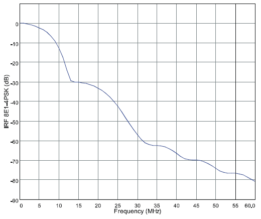
Interference Curves for Adaptive Modulation Radios
 TtoI and IRF curves are not used in adaptive modulation radio files. Transmit spectrum and receiver selectivity curves are required for these applications.
The diagram at the right shows the TX emission curves for several different modulation states in an adaptive modulation radio.
The differences between the curves start below the 25 dB point and the effects of
Noise Floor Calculations
The radio noise floor level is required to calculate receiver threshold degradation due to interference or co-channel operation. This is required for all applications - microwave, adaptive modulation and land mobile.
Provision is made for direct entry of the receiver noise floor. This is the preferred method. The noise floor can also be calculated indirectly using the receiver threshold and the corresponding CtoI ratio. In practice, these calculations result in slightly different values for each modulation state.
The following noise floor calculation methods are used in the program
Threshold to Interference ratio:
A modulated test signal is connected to the receiver and its level is adjusted to produce a BER of 1.0E-6. Denote this signal level as T dBm. Increase this level by 1 dB. An interfering signal using the same modulation and frequency is injected into the system and the level is adjusted so that the BER returns to 1.0E-6. Denote this interfering signal level as I dBm. The T/I ratio is then given by T - I.
The noise floor can be calculated as T - T/I + 5.868253 dBm
Carrier to interference ratio for a 3 dB degradation to the 10-6 BER receiver threshold:
A modulated test signal is connected to the receiver and its level is adjusted to produce a BER of 1.0E-6. Denote this signal level as T dBm. Increase this level by 3 dB. An interfering signal using the same modulation and frequency is injected into the system and the level is adjusted so that the BER returns to 1.0E-6. Denote this interfering signal level as I dBm. The C/I ratio is then given by T - I.
The noise floor can be calculated as T - C/I dBm
Carrier to interference ratio for a 3 dB degradation to the 10-3 BER receiver threshold:
A modulated test signal is connected to the receiver and its level is adjusted to produce a BER of 1.0E-3. Denote this signal level as T dBm. Increase this level by 3 dB. An interfering signal using the same modulation and frequency is injected into the system and the level is adjusted so that the BER returns to 1.0E-3. Denote this interfering signal level as I dBm. The C/I ratio is then given by T - I.
The noise floor can be calculated as T - C/I dBm
Noise Figure:
The noise floor can be calculated from the noise figure using the relationship KTBF where:
K is Boltzman’s constant, T is the absolute temperature in degrees Kelvin, B is the 3 dB bandwidth in Hertz and F is the noise figure expressed as a ratio
Using the AntRad Utility to Create Pathloss 5/6 Radio Files
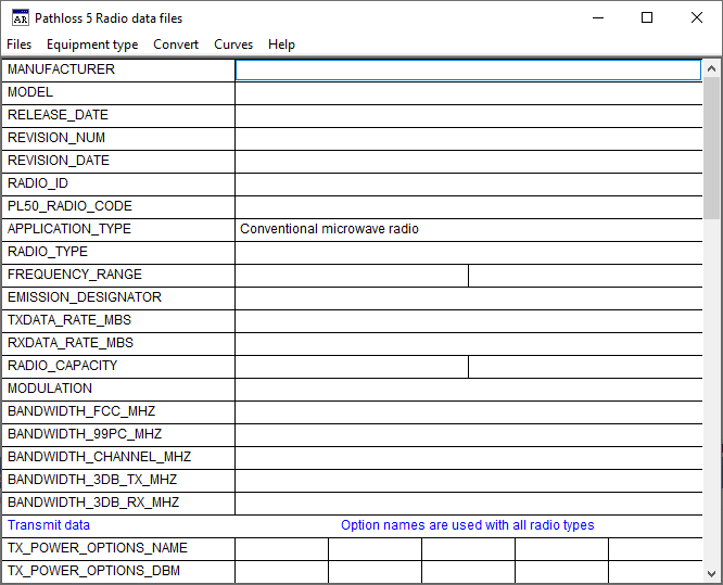 AntRad is used to create and edit radio data files. The main data entry form uses the same mnemonics as the ASCII text file described above. Lines with multiple entries have column separators.
The Files-Open menu selection will open all radio file versions including:
- Pathloss 4 ASCII raf files
- Pathloss 5/6 ASCII raf files
- Pathloss 4 binary mrs microwave radio files
- Pathloss 5/6 binary rsd radio files
Separate file save menu items are provided for ASCII and binary formats. Both of these use the version 5 formats.
To save in version 4 formats, use the Equipment type - Version 4 Radio data files menu item.
Access to the Adaptive Modulation and Antenna Coupling Unit data entry forms is by clicking their corresponding buttons.
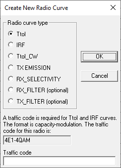
Radio Curves
Select the Curves menu item to create or edit curves. The first step is to specify the specific type of curve. Click the new button, select the curve type and click the OK button.
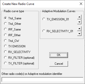
If a TtoI_Other or IRF_Other curve has been specified, then enter the name of the corresponding radio data file name. Multiple file names can be entered separated by a comma.
Editing Version 4.0 Interference curves
Version 4.0 used the concept of a traffic code to identify interference curves. This consisted of a concatenation of the channel capacity and the modulation e.g. 8E1-QPSK. The TtoI curve of this radio would be coded as TtoI_8E1-QPSK.
When a version 4.0 file is loaded into the AntRad program, a traffic code will be generated using the channel capacity and the modulation specified in the file. This will be compared to the coding on the TtoI curves. If the TtoI curve is coded with the same traffic code, the curve will be interpreted as a TtoI_Same curve.
If the T to I curve coding does not match the traffic code, the curve will be interpreted as a TtoI_Other curve.
Consider the example of a version 4 radio with a 8E1 capacity and QPSK modulation. The resulting traffic code is 8E1-QPSK. The data file has the following TtoI curves:
TtoI_8E1-QPSK - interfering radio has the same channel capacity and modulation. This curve will be coded as TtoI_Same
TtoI_4E1-QPSK - interfering radio has a different channel capacity or modulation. This curve will initially be coded as TtoI_Other 4E1-QPSK. The user must change the other code designation of 4E1-QPSK to the corresponding radio code i.e. the name of the binary file less suffix of the 4E1-QPSK radio.
The above step must be carried out for each TtoI_Other or IRF_Other curve. Select the curve in the drop down list and change the corresponding other codes in the edit control below the drop down list. The names in the drop down list will not change until the Create - edit radio curve dialog is closed and re-opened
Radio Data File Locking
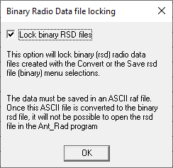
The AntRad program can open and edit binary and ASCII files. Provision has been made to inhibit opening and editing of binary files. In this case the master data record must be an ASCII file.
Select the Files - Lock binary rsd files menu selection. Click the Lock binary rsd files box and then click OK. When the binary file is saved, a “file locked” message will be present on the windows save file dialog.
Using Radio Data Files in the Pathloss Program
See Radio Data File Index for information on indexing and selecting Radio Data files in Pathloss.
Version 4 Radio Data Files
File Naming Convention
The radio data file name is used as a search field in a directory tree structure. The file names must be unique. The maximum radio file name length is 15 characters in version 4. Note that if several different transmit power options or receiver threshold options are required, then separate files must be provided.
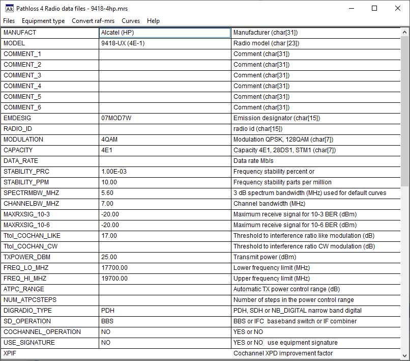
File Format
This section describes the Pathloss version 4 ASCII file format. These files use the suffix “raf” and must be converted to a binary format to used in the program. The file suffix of the binary file is always “mrs”. The conversion can be carried out in the Pathloss version 4 program or with the AntRad program.
The ASCII file consists or a Mnemonic and a value separated by a space or tab. The file format is given in the following table.
|
Mnemonic |
Size |
Description |
Example |
|
PLW40_RADIOSPECS |
* |
raf file identifier |
|
|
MANUFACT |
* char[35] |
radio manufacturer |
Acme Radio |
|
MODEL |
* char[23] |
radio model |
ASDH-64 |
|
COMMENT_1 |
char[35] |
optional comment |
|
|
COMMENT_2 |
char[35] |
optional comment |
|
|
COMMENT_3 |
char[35] |
optional comment |
|
|
COMMENT_4 |
char[35] |
optional comment |
|
|
COMMENT_5 |
char[35] |
optional comment |
|
|
EMDESIG |
char[23] |
emission designator |
2M50D7W |
|
RADIO_ID |
char[23] |
optional radio identifier |
ACM-64-01 |
|
MODULATION |
* char[23] |
modulation - see below |
64TCM |
|
CAPACITY |
* char[23] |
channel capacity |
STM1 |
|
DATA_RATE |
numeric |
data rate |
155.52 |
|
STABILITY_PRC |
numeric |
frequency stability in percent |
|
|
STABILITY_PPM |
numeric |
frequency stability in parts per million |
5 |
|
SPECTRMBW_MHZ |
* numeric |
spectrum 3db bandwidth in MHz used to create default TX emission and RX sensitivity masks |
18 |
|
CHANNELBW_MHZ |
numeric |
channel bandwidth in MHz |
20 |
|
MAXRXSIG_10-3 |
numeric |
maximum receive signal at BER 10-3 |
-12 |
|
MAXRXSIG_10-6 |
numeric |
maximum receive signal at BER 10-6 |
-10 |
|
TtoI_COCHAN_LIKE |
** numeric |
threshold to interference ratio like modulation (dB) |
26.8 |
|
TtoI_COCHAN_CW |
numeric |
threshold to interference ratio CW modulation (dB) |
25.0 |
|
TXPOWER_DBM |
* numeric |
transmit power (dBm) |
30.0 |
|
FREQ_LO_MHZ |
* numeric |
lower frequency limit (MHz) |
5900 |
|
FREQ_HI_MHZ |
* numeric |
upper frequency limit (MHz) |
6400 |
|
ATPC_RANGE |
numeric |
automatic TX power control range (dB) |
10 |
|
NUM_ATPCSTEPS |
numeric |
number of steps in the ATPC range |
5 |
|
DIGRADIO_TYPE |
PDH, SDH or NB_DIGITAL |
digital radio type -PDH, SDH or narrow band digital default is PDH |
SDH |
|
SD_OPERATION |
BBS or IFC |
space diversity type baseband switching or IF combining default is BBS |
IFC |
|
COCHANNEL_OPERATION |
YES or NO |
calculate using co-channel operation - default is NO |
YES |
|
USE_SIGNATURE |
YES or NO |
use signature (YES) or dispersive fade margin (NO) to calculate the selective outage default is NO |
YES |
|
XPIF |
numeric |
the XPD improvement factor of the XPIC device in co-channel operation |
17.0 |
|
XPD_XPI |
numeric |
the residual XPD of the XPIC device in co-channel operation |
42.0 |
|
IF_COMB_GAIN |
numeric |
the thermal fade margin improvement in dB produced by IF combining in space diversity |
3.0 |
|
LCOMB_FACTOR |
numeric |
the selective outage improvement factor produced by IF combining in space diversity |
10.0 |
|
BITS_BLOCK |
*** numeric |
bits per block (SDH) |
19940 |
|
BLOCKS_SEC |
*** numeric |
blocks per second (SDH) |
8000 |
|
ALPHA1 |
*** numeric |
errors per burst in the BER range from 10-3 to BERSES (SDH) |
10 to 30 20 typical |
|
ALPHA2 |
*** numeric |
errors per burst in the BER range from BERSES to the residual bit error rate (SDH) |
1 to 10 5 typical |
|
ALPHA3 |
*** numeric |
errors per burst below the residual bit error rate (SDH) |
1 |
|
SIGNATURE_DELAY_10-3 |
numeric |
signature echo delay in nanoseconds for a 10-3 BER |
6.3 |
|
SIGNATURE_WIDTH_10-3 |
numeric |
signature bandwidth width in MHz for a 10-3 BER |
28.0 |
|
SIGNATURE_MINPH_10-3 |
numeric |
signature null depth for a minimum phase echo at 10-3 BER |
23.4 |
|
SIGNATURE_NONMINPH_10-3 |
numeric |
signature null depth for a nonminimum phase echo at 10-3 BER |
23.4 |
|
SIGNATURE_DELAY_10-6 |
numeric |
signature echo delay in nanoseconds for a 10-6 BER |
6.3 |
|
SIGNATURE_WIDTH_10-6 |
numeric |
signature bandwidth width in MHz for a 10-6 BER |
28.3 |
|
SIGNATURE_MINPH_10-6 |
numeric |
signature null depth for a minimum phase echo at 10-6 BER |
21.7 |
|
SIGNATURE_NONMINPH_10-6 |
numeric |
signature null depth for a nonminimum phase echo at 10-6 BER |
21.7 |
|
SIGNATURE_DELAY_RBER |
numeric |
signature echo delay in nanoseconds for the residual BER |
6.3 |
|
SIGNATURE_WIDTH_RBER |
numeric |
signature bandwidth width in MHz for the residual BER |
28.7 |
|
SIGNATURE_MINPH_RBER |
numeric |
signature null depth for a minimum phase echo at the residual BER |
19.5 |
|
SIGNATURE_NONMINPH_RBER |
numeric |
signature null depth for a nonminimum phase echo at the residual BER |
19.5 |
|
SIGNATURE_DELAY_SES |
numeric |
signature echo delay in nanoseconds for the SES BER |
6.3 |
|
SIGNATURE_WIDTH_SES |
numeric |
signature bandwidth width in MHz for the SES BER |
28.0 |
|
SIGNATURE_MINPH_SES |
numeric |
signature null depth for a minimum phase echo at the SES BER |
23.4 |
|
SIGNATURE_NONMINPH_SES |
numeric |
signature null depth for a nonminimum phase echo at the SES BER |
23.4 |
|
DISPFM_10-3 |
numeric |
dispersive fade margin for the 10-3 BER |
48 |
|
DISPFM_10-6 |
numeric |
dispersive fade margin for the 10-6 BER |
45 |
|
DISPFM_SES |
numeric |
dispersive fade margin for the SES BER |
46.2 |
|
DISPFM_RBER |
numeric |
dispersive fade margin for the residual BER |
43 |
|
RXTHRESH_10-3 |
* numeric |
receive threshold level (dBm) at the 10-3 BER |
-73.5 |
|
RXTHRESH_10-6 |
* numeric |
receive threshold level (dBm) at the 10-6 BER |
-70.0 |
|
RESIDUAL_BER |
*** numeric |
residual bit error rate |
1.0E-10 |
|
RXTHRESH_RBER |
*** numeric |
receive threshold level (dBm) at the residual BER |
-66.0 |
|
SES_BER |
*** numeric |
SES bit error rate |
4.6E-4 |
|
RXTHRESH_SES_BER |
*** numeric |
receive threshold level (dBm) at the SES BER |
-73.1 |
|
TtoI_ |
data |
threshold to interference curve |
|
|
TX_EMISSION |
data |
transmit emission curve |
|
|
RX_SELECTIVITY |
data |
receive selectivity curve |
|
|
RX_FILTER |
data |
receive filter curve information only |
|
|
TX_FILTER |
data |
transmit filter curve information only |
|
|
IRF_ |
data |
interference reduction factor curve. Use either T to I or IRF |
|
Several equipment / calculation options are included in the radio data file:
DIGRADIO_TYPE SDH - Permissible values are PDH, SDH or NB_DIGITAL(narrow band digital). These options only affect the formatting of the data entry forms in the microwave worksheet. For example, signature data or the dispersive fade margin cannot be accessed with the NB_DIGITAL radio type set.
SD_OPERATION - Permissible values are IFC for IF combining and BBS for baseband switching. This option automatically set the space diversity improvement calculation to IF combining or baseband switching. The default value is baseband switching.
COCHANNEL_OPERATION - Permissible values are YES or NO. This sets the Co-channel operation option in the Reliability Options dialog box. The default value is NO.
USE_SIGNATURE - Permissible options are YES for selective fading calculations using the equipment signature or NO to use the dispersive fade margin and dispersive fade occurrence factor. Note that this options has the effect of calculating diversity improvement is strict accordance with P.530.
The ASCII file is created by adding the entry or value after the mnemonic. Leave at least one space between the mnemonic and the entry.
- The mnemonic lines can be in any order and blank lines are allowed in the file; however the file identifier "PLW40_RADIOSPECS" must be the first entry in the file.
- If there is no entry after the mnemonic, the line is ignored. Therefore, it is not necessary to erase any unused entries.
- If a duplicate mnemonic line exists, the value of the last one in the file will be used. Frequency stability can be expressed as either a percent or in parts per million. The value used will be the last one in the file.
Modulation
The modulation is used to determine default threshold to interference curves. The format must be as follows:
[number of levels][modulation type] e.g. 64QAM
No spaces or dashes are allowed. The modulation type must be one of the following:
FSK frequency shift keying
CPSK coherent demodulation phase shift keying
DPSK differential demodulation phase shift keying
QAM quadrature amplitude modulation
QPR quadrature partial response
TCM trellis code modulation - this is interpreted as QAM
QPSK quadrature phase shift keying - this is interpreted as 4DPSK
MSK minimum shift keying - this is interpreted as 2FSK
Channel Capacity
Channel capacity is expressed in terms of the digital hierarchy, (e.g. 1DS3, 8E1).
Traffic Code
The channel capacity and modulation are combined to form a unique radio descriptor using the following format:
[channel capacity]-[modulation] e.g. 1DS3-64QAM
This identifier is used to compare the characteristics of an interfering transmitter with the receiver.
The traffic code does not appear in the radio data file as a unique entry. It is derived from the channel capacity and modulation.
In the case of analog radios, the traffic code must be specified using the format below:
[CAPACITY]-ANALOG e.g. 600CH-ANALOG
The capacity prefix (600CH) is not used.
Threshold to Interference Curves
The mnemonic ToI_ indicates that T to I data follows. There can be any number of T to I curves in a radio data file. Each curve can represent the interfering effects of different transmitter modulations and channel capacities. In order to differentiate between these curves, the TtoI_ mnemonic is followed by the traffic code of the interfering transmitter.
For the special case of a T to I curve for a carrier wave interfering transmitter, the traffic code must be CW.
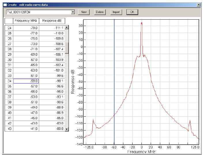
The number of points of data follows the mnemonic - traffic code combination. The data must be in ascending order of frequency and there must not be any duplicate frequencies or blank lines. Each line contains a frequency followed by the T to I value. The frequency must be relative to the operating frequency. The data can be symmetrical or asymmetrical. The following is an example of the data entry format of an 8DS1 receiver using 128TCM modulation interfered with by a similar radio.
 TtoI_8DS1-128TCM 171
-125.000 -143.6
-123.000 -142.8
-121.000 -141.0
....
-1.000 30.0
-.800 34.0
-.600 35.0
-.400 34.3
-.200 32.4
0.000 34.0
.200 33.0
.400 35.5
.600 35.5
.800 33.0
1.000 33.0
....
121.000 -142.9
123.000 -143.8
125.000 -145.1
The first line "TtoI_8DS1-128TCM 171" indicates that this is a T to I curve of 171 points. The interfering transmitter has the same modulation and channel capacity as the receiver.
Interference Reduction Factor Curves
The mnemonic IRF_ indicates that interference reduction factor (IRF) data follows. There can be any number of IRF curves in a radio data file. Each curve can represent the interfering effects of different transmitter modulations and channel capacities. In order to differentiate between these curves, the IRF mnemonic is followed by the traffic code of the interfering transmitter.
The number of points of data follows the mnemonic - traffic code combination. The data must be in ascending order of frequency and there must not be any duplicate frequencies or blank lines. Each line contains a frequency followed by the IFR value. The frequency must be relative to the operating frequency. The data can be symmetrical or asymmetrical. The following is an example of the data entry format for a 8E1 4PSK receiver (8E1-4PSK) interfered with similar modulation:
 IRF_8E1-4PSK 61
0.0 0.00
1.0 -0.11
2.0 -0.42
.....
58.0 -78.55
59.0 -79.70
60.0 -80.90
The first line "IRF_8E1-4PSK 61” indicates that this is an IRF curve of 33 points. The interfering transmitter has the same modulation and channel capacity as the receiver.
Transmitter Emission Data
The mnemonic TX_EMISSION indicates that the data for the transmitter emission spectrum follows. The absolute values of the power density or the measurement bandwidth are not important. The file conversion process will normalize the data such that the total power over the frequency band is equal to unity. The chart display of the spectrum is based on a total power of one watt and a measurement bandwidth of 4 KHz. This means that the data values in the ASCII file may not be the same as the displayed values.
The number of points follows the mnemonic TX_EMISSION on the same line. The data must be in ascending order of frequency and there must not be any duplicate frequencies or blank lines. Each line contains a frequency followed by the emission level. The frequency must be relative to the operating frequency. The data can be symmetrical or asymmetrical.
Receiver Selectivity
The mnemonic RX_SELECTIVITY indicates that the receiver selectivity data follows. This is the composite receiver selectivity including RF, IF and Nyquist filtering. Do not use RF or IF filtering alone.
The number of points follows the mnemonic RX_SELECTIVITY on the same line. The data must be in ascending order of frequency and there must not be any duplicate frequencies or blank lines. Each line contains a frequency followed by the selectivity expressed in dB. The frequency must be relative to the operating frequency. The data can be symmetrical or asymmetrical.
Default Interference Parameters
In many cases, the required T to I and TX emission curves will not be available. This section describes the techniques used to handle these situations. The analysis uses the 3 dB bandwidth of the transmit spectrum and the type of modulation. Both of these must be specified in the radio data file.
When a radio data file is generated from the user's ASCII text file, a default transmit emission mask and a default receiver selectivity mask is always created in accordance with Annex B of TIA /EIA Telecommunications Systems Bulletin TSB-10G (Interference Criteria for Microwave Systems). These masks are based on the FCC Rules and Regulations, § 101.111 - emission limitations for digital fixed point to point operation below 15 GHz as stated below:
For operating frequencies below 15 GHz, in any 4 KHz band, the center frequency of which is removed from the assigned frequency by more than 50 percent up to and including 250 percent of the authorized bandwidth: As specified by the following equation but in no event less than 50 decibels: (Attenuation greater than 80 decibels is not required.)
(1) ![]()
where:
A = Attenuation (in~ decibels) below the mean output power level
P = Percent removed from the carrier frequency
B = Authorized bandwidth in MHz
Default TX Emission Mask
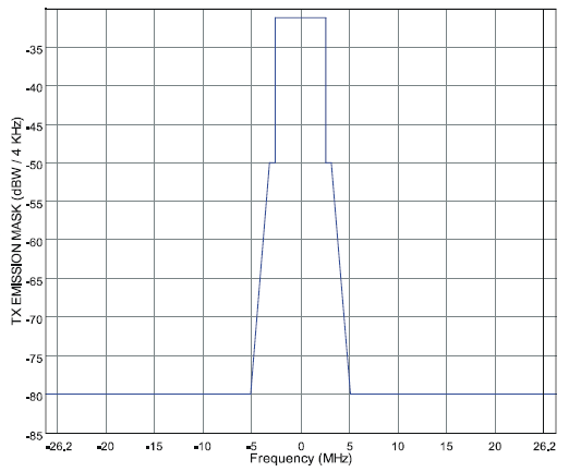 In place of the authorized bandwidth (channel bandwidth), the 3 dB bandwidth of the transmit spectrum is used. For frequencies from 50 percent to 250 percent removed from the carrier frequency, the power spectral density of the interference follows the FCC Mask. In other words, each 4 KHz of spectrum contains -A dBW of power. To complete the definition of the default TX emission mask, the following assumptions are made:
- Emission is -80 dBW/4kHz for frequencies from 250 percent to 500 percent removed from the carrier frequency
- The emission is zero for frequencies more than 500 percent removed from the carrier frequency.
- For frequencies from 0 to 50 percent removed from the carrier frequency, each 4 kHz of spectrum contains an equal amount of power such that the total power in the signal (from 0 to 500 percent removed from the carrier frequency) is 1 Watt.
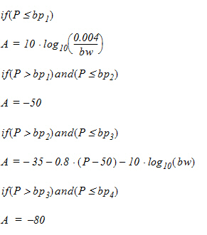
The mask is generated from the following break points:
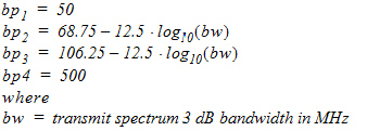
and the equations below:
Default Receiver Selectivity Mask
The default receiver selectivity mask has the identical shape as the default TX emission mask. However, it is shifted so that for frequencies from 0 to 50 percent removed from the carrier frequency, the filter attenuation is zero.

Using the AntRad Utility to create Version 4 Radio Data Files
The AntRad utility is used to create and edit Version 4 and 5 radio data files. Select the Equipment type - Version 4 radio data files menu item. The data entry form uses the same mnemonics as the ASCII text file described above. A third column is provided for additional information.
A single data entry per line is used. The Files-Open menu selection will open all radio file versions including:
- Version 4 ASCII raf files
- Version 5 ASCII raf files
- Version 4 binary mrs microwave radio files
- Version 5 binary rsd radio files
Separate file save menu items are provided for ASCII and binary formats. Both of these use the version 4 formats.
Radio Curves
Select the Curves menu item to create or edit curves. The first step is to specify the specific type of curve. Click the new button, select the curve type and click the OK button.
If a TtoI_Other or IRF_Other curve has been specified, then enter the name of the corresponding radio data file name. Multiple file names can be entered separated by a comma.
TtoI and IRF Interference curves
A traffic code is used to identify the characteristics of the interfering transmitter. This consists of a concatenation of the channel capacity and the modulation e.g. 8E1-QPSK. The TtoI curve of this radio would be coded as TtoI_8E1-QPSK.
Antenna Data Files
Antenna data files use and industry standard NSMA - TIA standard for ASCII antenna data files. This is the same format used in Pathloss 4 for microwave and VHF-UHF antennas. Pathloss 5/6 use a single binary format for all application types.
File Naming Convention
The antenna data file name without the extension is referred to as an antenna code. This code is used as a key field in a lookup table which implies that the file names must be unique. The maximum antenna code name length is 47 characters for Pathloss 5/6 and 15 characters for Pathloss 4.
File Formats
Antenna data files use the industry standard format defined by:
National Spectrum Managers Association (NSMA) https://www.nsma.org/
Antenna Systems
Standard Format for Digitized Antenna Patterns
Recommendation WG16.99.050
and
Telecommunications Industry Association (TIA) https://tiaonline.org
Terrestrial Land Mobile Radio
Antenna Systems
Standard Format for Digitized Antenna Patterns
TIA-804-A
In addition the program also supports the older NSMA "Standard Format for Electronic Transfer of Terrestrial Antenna Pattern Data", details of which are provided later in this section.
The antenna data files must be converted to a binary format to be used in the Pathloss program. This operation is carried out in the AntRad program.
Version 4.0 used different binary file formats for microwave and VHF-UHF antenna data files with the file suffixes “mas” and “vas” respectively. Version 5.0 uses a single binary file for all antennas with the suffix “asd”. To accomplish this, one of the “reserved for future use” fields FIELD5 is used for the antenna technology. These technologies are loosely defined as aperture (parabolic) and dipole. The difference between the two definitions is in the antenna orientation. Aperture antennas are assumed to be oriented in both azimuth and elevation which results in zero orientation loss as the default. Dipole antenna are assumed to be oriented in azimuth only with the elevation in a horizontal plane. The program calculates the orientation loss using the vertical antenna pattern and the actual vertical angle of the signal.
All existing Pathloss 4 binary antenna data files can be used in the version 5 and 6 program without modification.
Alternate NSMA Antenna Data File Format
The file consists of ten header lines followed by the data for the various polarization combinations. There must be exactly ten lines as a blank line is interpreted as "no entry" for that field.
Line Description Size

1 Antenna manufacturer [30]

2 Model number [30]

3 Comment [30]

4 FCC ID number [16]

5 Reverse pattern m number [16]

6 Date of data [16]

7 Manufacturer ID number [16]

8 Frequency range [16]

9 Mid-band gain [16]

10 Half-power beam width [16]
The header information is followed by the polarization combination and the number of data points. This is followed by the data expressed as the angle and response. The following polarization designators are used:
HH, HV, VV, VH in the horizontal plane
ELHH, ELHV, ELVV, ELVH in the vertical plane
The antenna response is listed as dB below the main lobe response and is a negative value. A partial example of an the antenna pattern file is shown below:
MARK ANTENNA PRODUCTS Inc.

MHP-100A120D

(none)

M15028

M15027

11-25-85

NONE

10700-11700 MHZ

48.4 dB

0.6 Deg

HH 39

-180 -88

-160 -88

¯ ¯

0 0

¯ ¯

160 -88

180 -88

HV 33

-180 -89

-170 -89

¯ ¯

0 -36

¯ ¯

170 -89

180 -89

VV 39

-180 -88

-160 -88

¯ ¯

0 0

¯ ¯

160 -88

180 -88

VH 33

-180 -89

-170 -89

¯ ¯

0 -36

¯ ¯

170 -89

180 -89

ELHH 7

-4 -36

¯ ¯

0 0

¯ ¯

4 -36

ELHV 11

-4.5 -63.4

¯ ¯

0 -36

¯ ¯

4.5 -63.4

ELVV 7

-4 -36

¯
Using AntRad to Create Antenna Data Files
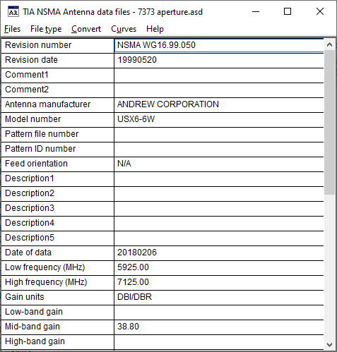 Use AntRad to edit, create and convert antenna data files. The program starts in the radio data files screen. Select File type - Antenna data files from the menu bar. There are several points to note in this data entry form:
- The description of the entry is used instead of the mnemonic. For example “Low-band Gain” is used instead of LWGAIN and “Azimuth Beam width (deg) is used instead of AZWIDT. The mnemonics are used in the ASCII files.
- The Revision number field (REVNUM) and the Revision date field (REVDAT) refer to revisions to the standard format. These are not used and serve only as file type identifiers
- The fields associated with antenna discrimination curves are not included in these forms. These are created - edited under the Curves section
- The Files - Open menu item opens all antenna file formats. These include the ASCII standard and the old ASCII standard, the version 4.0 binary mas and vas files and the version 5.0 asd files.
- The binary antenna data files do not contain all of the information in the ASCII file. Only the following items are included in the binary file.
- manufacturer, model, description antenna technology, feed horn orientation and the date of the data file
- mid band gain, diameter, 3 dB beam widths, electrical downtilt, radome loss, frequency range
- the type of antenna pattern (typical or envelope) and all azimuth and elevation pattern data
- Files can be saved in the version 5.0 asd binary format or the ASCII standard format. Only the binary version can be used with the Pathloss program.
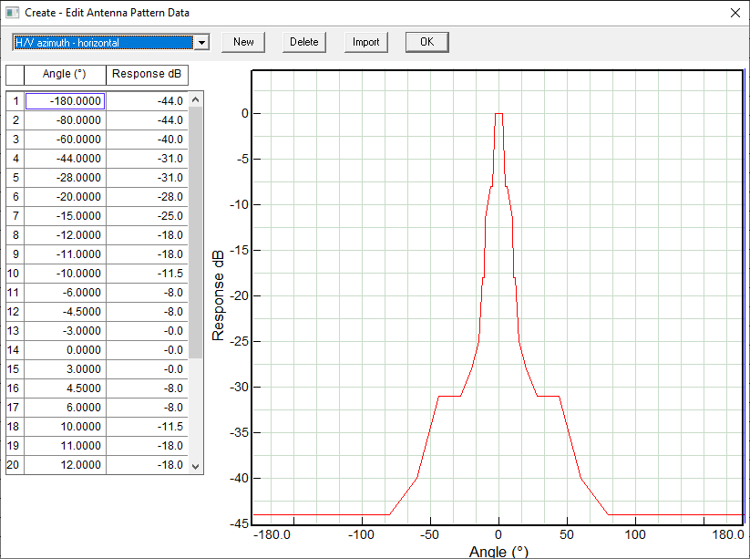
 Create - Edit Antenna Pattern Data
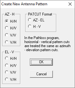
Select Curves on the Antenna data files menu bar. The drop down list contains the names of the antenna patterns using the following naming convention:
- H/H - Horizontal polarized port response to a horizontally polarized signal
- H/V Horizontal polarized port response to a vertically polarized signal
- V/V Vertical polarized port response to a vertically polarized signal
- V/H Vertical polarized port response to a horizontally polarized signal
The above designations can be used in either the horizontal or vertical planes
The data is presented in two columns: angle followed by the antenna response.
In the horizontal plane, the angle starts from -180º (defined as the left side of the antenna) and increases to 0º on the antenna boresight. The angle then increases to +180º, thereby covering the full 360º of the antenna pattern.
In the vertical plane, the angle starts at some negative value defined as the antenna response below the antenna boresight and increases to 0º on the antenna boresight. The angle then increases to some positive value which is above the antenna boresight. For microwave antennas the range is typically between -5º to +5º which results in a 10º range centered about the main beam. For dipole antennas, the elevation data is presented over -180º to +180º range.
The antenna response is listed as dB below the main lobe response and must be entered as a negative value.
To create a new curve, click the New button and define the type of curve. The curve data can be imported from a text file, Click the Import button and load the text file. The procedure uses the standard text import utility defined in the section on general program operation.
Note that the associated mnemonics are not used to create the antenna pattern curve. These are written to the standard ASCII file.
File Conversion ASCII ADF to binary ASD
In most cases, antenna manufacturers will supply the data files in the standard ASCII format and the AntRad program will only be used to convert the files to the binary asd format.
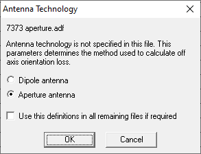
In the case of a single file, the procedure is to open the ASCII file (Files - Open) and review the data for completeness. In particular, ensure that the antenna technology field is set and in the case of microwave antennas the antenna diameter has been entered in either the antenna width or height field.
 For batch conversions, select the Convert menu item. A standard windows multi select file open dialog is used to select the required files. When the Open button is clicked a file save dialog appears. This allows the user to specify the directory to save the binary files in. The default is save the binary files in the same directory as the ASCII files. The file name in this dialog is not used. The binary file names will always be the same as the ASCII file names with the extension in a batch conversion.
If the antenna technology is not specified, the dialog on the right will appear prompting for the technology and to use this technology for all files in the conversion.