Co-channel (XPIC) Operation
The capacity of a link can be effectively doubled by simultaneously transmitting a channel on both horizontal and vertical polarization. This mode is referred to as co-channel or XPIC operation. The viability of the link will be determined by the increased outage time resulting from the mutual interfering effect of this operation when the cross polarized discrimination degrades during multipath and high intensity rain conditions.
Co-channel operation is invoked by checking this option under Configure - Options - Calculation Option - Transmission Calculations - Multipath Fading Method.
Check the Enable Co-channel Operation and select from the following 2 methods:
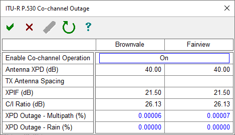
ITU-R P.530 Method - This method calculates the additional outage due to the reduction of Cross Polarized Discrimination (XPD) due to multipath activity and precipitation.
A C/I ratio value is required for the ITU-R P.530 method. If a radio file is loaded, the C/I will be read from the Adaptive Modulation data table for each modulation state.
If there are no C/I values defined in the Adaptive Modulation data table, the program will calculate the values by subtracting the noise floor from each modulation states 10-6 threshold.
More information on how the noise floor is calculated can be found at: Noise Floor Calculations
The C/I ratio value displayed in the window is for the currently selected (reference) modulation state.
If there is no radio file loaded, a C/I value can be entered manually in the field.
The ITU method requires that a rain calculation be included. The rain calculation is automatically enabled when the ITU-R P.530 Method is selected. The warning messages for the ITU and Crane rain methods are suppressed.
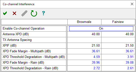
Pathloss 5 Method - This method calculates the threshold degradation caused by the interfering cross polarized signal. The resulting degraded fade margin (flat fade margin) is then used in the overall outage calculations. This is the same method used in previous versions of Pathloss.
Both methods use the following parameters:
Antenna XPD - This will be automatically entered if the antenna data entry form contains an antenna code. Otherwise the user can enter a value. a typical Antenna XPD would be 30dB
TX antenna spacing - If separate antennas are used for vertical and horizontal polarization, enter the vertical separation between antennas. Otherwise, this entry must be blank (F3 key).
XPIF - This value is automatically filled in from the currently loaded radio file. If the radio has multiple modulations states, the XPIF value for the reference state is used. The reference state is selected when the radio file is loaded, and it is highlighted in blue on the screen. The value can also be entered manually if no file is available, a typical XPIF value would be about 20dB.